
Thermally-driven digital micro-fluidic chip, manufacturing method and working method thereof

A technology of digital microfluidics and a manufacturing method, applied in the field of microfluidics, can solve the problems of high cost, easily damaged hydrophobic layer, unfavorable repeated use, etc., and achieve the effects of simple structure, low cost, and large driving force

Pending Publication Date: 2018-05-04
BOE TECH GRP CO LTD +1
View PDF1 Cites 10 Cited by
  • Summary
  • Abstract
  • Description
  • Claims
  • Application Information

AI Technical Summary

Problems solved by technology

Therefore, the chip process is difficult and expensive
At the same time, when the chip is cleaned, it is easy to damage the hydrophobic layer, which is not conducive to repeated use

Method used


Image

  • Thermally-driven digital micro-fluidic chip, manufacturing method and working method thereof
  • Thermally-driven digital micro-fluidic chip, manufacturing method and working method thereof
  • Thermally-driven digital micro-fluidic chip, manufacturing method and working method thereof

Examples


Embodiment Construction

[0043] Exemplary embodiments will now be described more fully with reference to the accompanying drawings. However, the exemplary embodiments can be implemented in a variety of forms, and should not be construed as being limited to the examples set forth herein; on the contrary, the provision of these embodiments makes the present invention more comprehensive and complete, and fully comprehends the concept of the exemplary embodiments. To convey to those skilled in the art. The same reference numerals in the figures represent the same or similar structures, and thus their detailed descriptions will be omitted.

[0044] Although relative terms such as "upper" and "lower" are used in this specification to describe the relative relationship between one component of an icon and another component, these terms are used in this specification only for convenience, for example, according to the drawings. The direction of the example described. It can be understood that if the device of ...


PUM


Abstract

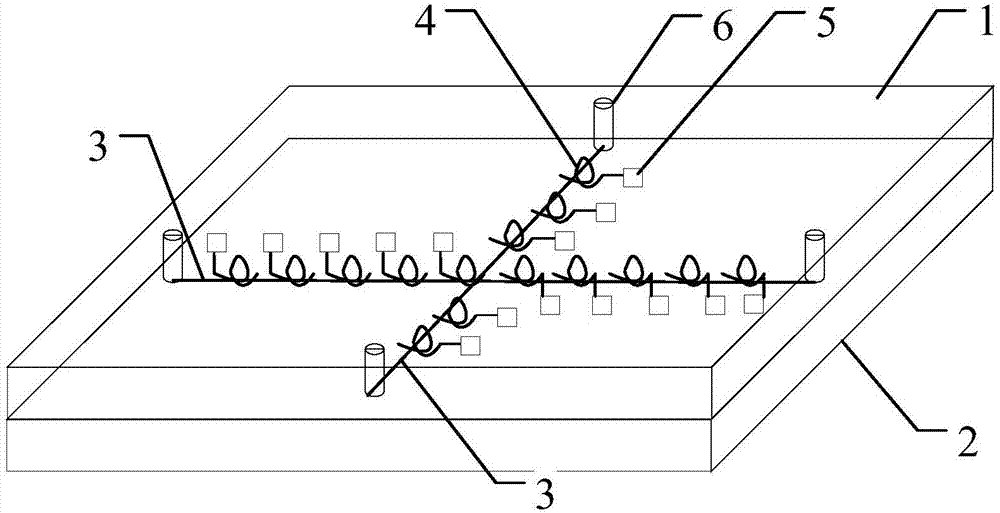
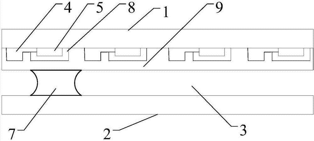
The invention relates to the technical field of micro-fluidic control, and discloses a thermally-driven digital micro-fluidic chip, a manufacturing method and a working method thereof. The thermally-driven digital micro-fluidic chip comprises a first base plate, a second base plate, a capillary tube, a plurality of first electric-heating assemblies and a plurality of first switch elements, whereinthe second base plate is opposite to the first base plate; the capillary tube is arranged on the first base plate and / or the second base plate; the first electro-heating assemblies are arranged on the first base plate, and are distributed in a spaced mode in an extending direction of the capillary tube; and each first switch element is connected in a current loop in which one first electric-heating assembly is located to receive a control signal for controlling closing of the current loops on which the first electric-heating assemblies are located. In case of not arranging a water dredging layer on the inner surface of the capillary tube, liquid drops move in an oriented mode in the capillary tube for being recycled. Meanwhile, tension on the surfaces at the two sides of each liquid dropis changed by heating to drive the liquid drops to move, so that driving force is relatively great.

Description

Technical field [0001] The invention relates to the technical field of microfluidics, in particular to a thermally driven digital microfluidic chip, a manufacturing method and a working method. Background technique [0002] Microfluidic chip technology integrates basic operation units such as sample preparation, reaction, separation, and detection onto a centimeter-scale chip. This technology greatly reduces the cost of samples and improves detection efficiency. It has been highly sought after in recent years and is widely used in biology, chemistry, medicine and other fields. [0003] At present, the mainstream microfluidic chip drive method is electrode drive, also called voltage digital microfluidic control. Voltage digital microfluidics is to place droplets in a capillary channel with a hydrophobic layer. With the help of electrowetting, a voltage is applied between the droplet and the electrode under the hydrophobic layer to increase the position of the electrode droplet and...

Claims


Application Information

Patent Timeline
Patent Type & Authority Applications(China)
IPC IPC(8): B01L3/00
CPCB01L3/502707B01L3/50273B01L3/502784B01L2200/12B01L2300/0838B01L2300/0887B01L2400/0442B01L2300/0816B01L2400/0448
Inventor 吕明阳李月李金钰李彦辰赵宇王冬侯少军冯大伟郭旺
Owner BOE TECH GRP CO LTD
Learn More