
Multifunctional emulsification tank

An emulsification tank, multi-functional technology, applied in chemical instruments and methods, chemical/physical processes, dissolution, etc., can solve problems such as poor emulsification effect, increased noise, vibration, increased energy consumption, etc.

Inactive Publication Date: 2018-05-01
成都尚智恒达科技有限公司
View PDF1 Cites 3 Cited by
  • Summary
  • Abstract
  • Description
  • Claims
  • Application Information

AI Technical Summary

Problems solved by technology

The emulsification tank is suitable for the production of industrial products such as cosmetics, medicine, food, chemistry, dyeing, printing ink, etc., especially for materials with high viscosity and high solid content. There is a stirring device, and the matrix sticking to the wall will fail to stir because it is attached to the wall, resulting in uneven stirring and poor emulsification effect.
[0003] Chinese patent CN201720271921.0 discloses an emulsification tank for paste preparation, including a tank body, the top of the tank body is respectively provided with a feed inlet, a hanger rotating motor and a stirring shaft motor, and the bottom of the tank body is provided with a discharge port , the tank is provided with a hanger connected with the hanger rotating motor and a stirring shaft connected with the stirring shaft motor, the stirring shaft is arranged in the hanger, and the side of the hanger is provided with There are several side wall scrapers, and the side wall scrapers are in conflicting connection with the inner side wall of the tank body. The hanger and the side wall scrapers are directly provided with circumferential slots, and the side wall scrapers can pass through the The circumferential draw-in groove rotates with the side of the hanger as the axis, and a number of stirring plates are arranged on the stirring shaft. In this invention, the matrix on the inner wall of the emulsification tank is scraped off by setting the wall hanging plate and the hanger rotating motor. However, there are two motors for driving the scraper and the stirring shaft, that is, the hanger rotating motor and the stirring shaft motor. The simultaneous operation of the two motors not only increases energy consumption, but also increases noise, vibration, etc., which is not conducive to energy saving and environmental protection. Into two makes the structure complex and increases the cost

Method used


Image

  • Multifunctional emulsification tank

Examples


Embodiment 1

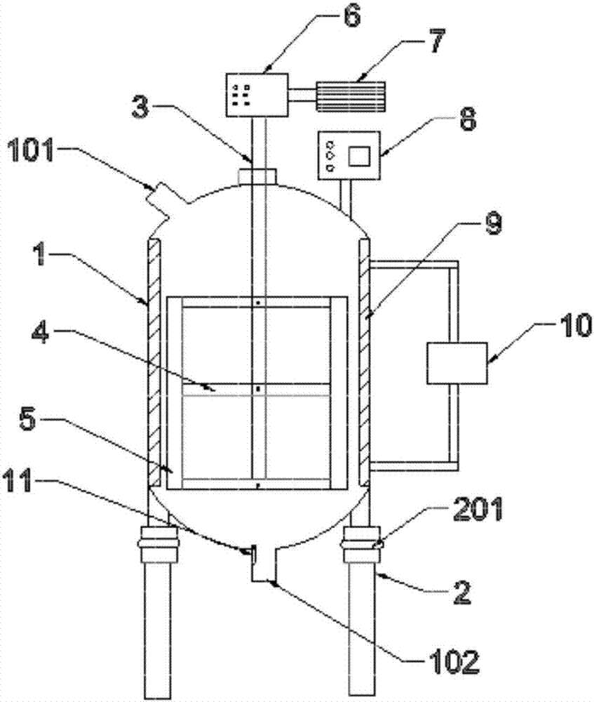
[0015] A multifunctional emulsification tank, comprising a tank body 1, a feed inlet 101 at the top of the tank body 1, and a discharge port 102 at the bottom of the tank body 1; A set of stirring blades 4 is provided, and the two ends of the stirring blades 4 can perform telescopic movement along the direction of the stirring shaft 3, and a scraper 5 is arranged at both ends of the stirring blades 4, and the stirring shaft 3 protrudes from the tank body 1, and one end is sequentially connected with a gearbox 6 and a stirring motor 7, a control panel 8 is arranged on the top of the tank body 1, and the control panel 8 is electrically connected with the stirring blade 4, the gearbox 6 and the stirring motor 7.

[0016] Working principle: Since the stirring blade 4 is retractable, it needs to be stirred at the beginning of emulsification. The gearbox 6 adjusts the stirring speed of the stirring shaft 3, and the stirring blade 4 expands and contracts in the direction of the stirri...


PUM


Abstract

The invention discloses a multifunctional emulsification tank, which comprises a tank body, a feeding opening and a discharging opening, wherein the feeding opening is formed in the top of the tank body; the discharging opening is formed in the bottom of the tank body; a stirring shaft is arranged in the tank body; a group of stirring blades is arranged on the stirring shaft; the two ends of the stirring blade can do telescopic movement in the direction along the stirring shaft; a scraping plate is arranged at each of the two ends of the stirring blade; one end, extending of the tank body, ofthe stirring shaft is sequentially connected with a gearbox and a stirring motor; a control panel is arranged on the top of the tank body; the control panel is electrically connected with the stirringblade, the gear box and the stirring motor. The stirring and wall hanging actions can be simultaneously completed by using one motor; the energy sources are saved; the cost output is reduced.

Description

technical field [0001] The invention relates to the technical field of emulsification industry, in particular to a multifunctional emulsification tank. Background technique [0002] The role of the emulsification tank is to dissolve one or more materials (water-soluble solid phase, liquid phase or jelly, etc.) in another liquid phase and hydrate it into a relatively stable emulsion. It is widely used in the emulsification and mixing of edible oils, powders, sugars and other raw and auxiliary materials. Some coatings and paint emulsification dispersions use emulsification tanks, especially for some difficult-to-contain colloidal additives. The emulsification tank is suitable for the production of industrial products such as cosmetics, medicine, food, chemistry, dyeing, printing ink, etc., especially for materials with high viscosity and high solid content. There is a stirring device, and the matrix sticking to the wall will fail to stir because it is attached to the wall, re...

Claims


Application Information

Patent Timeline
IPC IPC(8): B01F7/32B01F15/00B01F15/06B01F27/96
CPCB01F27/0542B01F27/092B01F27/091B01F27/13B01F27/96B01F35/123B01F35/2115B01F35/221422B01F35/2215B01F35/43B01F2035/99B01F35/92
Inventor 史晓莉
Owner 成都尚智恒达科技有限公司
Learn More