
A display device and testing method thereof

A technology for display devices and test pins, applied in measuring devices, electronic circuit testing, measuring electricity, etc., can solve problems such as short circuits, display panel damage, misaligned electrical connections, etc.

Active Publication Date: 2020-01-21
WUHAN TIANMA MICRO ELECTRONICS CO LTD
View PDF9 Cites 0 Cited by
  • Summary
  • Abstract
  • Description
  • Claims
  • Application Information

AI Technical Summary

Problems solved by technology

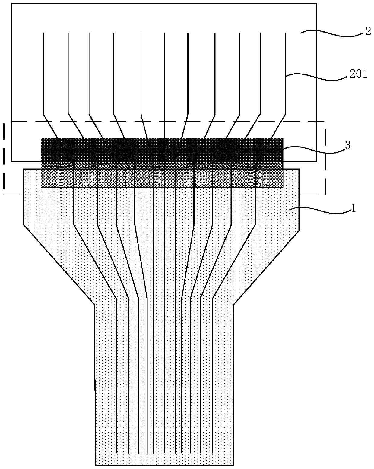
[0004] However, for the above-mentioned VT test method, if the connection pins of the FPC end and the connection pins of the FOG end are not connected accurately, that is, the two are not aligned with the electrical connection, after the test signal is loaded, a short circuit is very likely to occur, and the charged FPC It is easy to burn the ITO electrode and FPC at the FOG end of the display panel, causing damage to the display panel

Method used


Image

  • A display device and testing method thereof
  • A display device and testing method thereof
  • A display device and testing method thereof

Examples


Embodiment Construction

[0026] The present invention will be further described in detail below in conjunction with the accompanying drawings and embodiments. It should be understood that the specific embodiments described here are only used to explain the present invention, but not to limit the present invention. In addition, it should be noted that, for the convenience of description, only some structures related to the present invention are shown in the drawings but not all structures. Throughout this specification, the same or similar reference numerals represent the same or similar structures, elements or processes. It should be noted that, in the case of no conflict, the embodiments in the present application and the features in the embodiments can be combined with each other.

[0027] An embodiment of the present invention provides a display device, including a flexible circuit board, a display panel, and a test module. The pin area of ​​the flexible circuit board includes a plurality of first...


PUM


Abstract

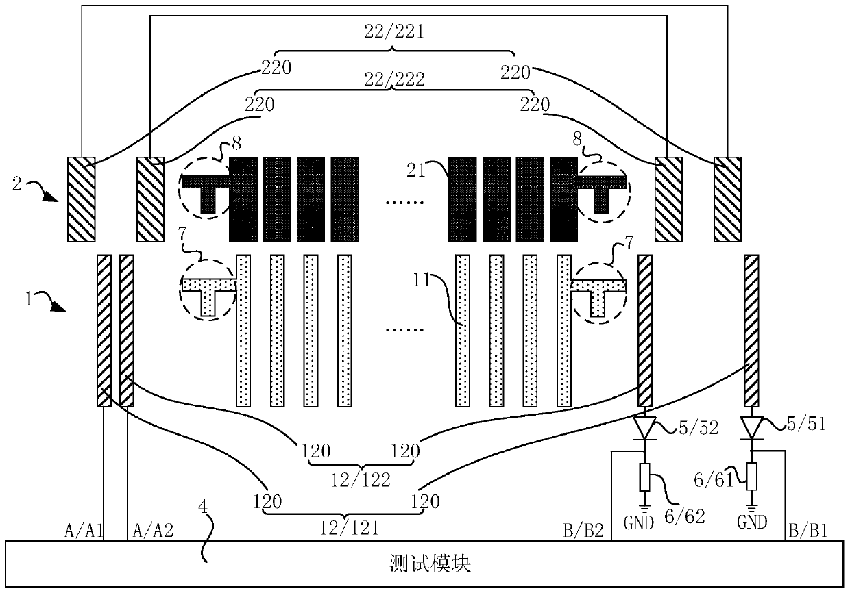
The invention discloses a display device and a test method thereof. Each first test pin group of a flexible circuit board of the display device comprises two first test pins, each second test pin group of a display panel comprises two electrically-connected second test pins, when a first connection pin is in alignment electrical connection with a corresponding second connection pin, the first testpins and the corresponding second test pins are not electrically connected, when the first connection pin and the corresponding second connection pin are not in alignment electrical connection, the first test pins are electrically connected with the corresponding second test pins, when the first connection pin is in alignment electrical connection with the corresponding second connection pin, thefirst test pins of one first test pin group are at the left side of the corresponding second test pins, and the first test pins of another first test pin group are at the right side of the corresponding second test pins. The test device is advantaged in that detecting whether the first connection pins are in alignment electrical connection with the corresponding second connection pins is realized.

Description

technical field [0001] Embodiments of the present invention relate to the field of display technology, and in particular, to a display device and a testing method thereof. Background technique [0002] The display test (Visual Test, VT) of the display panel is a very important link in the production process of the display panel. After the display panel is produced, the scanning signal line, data signal line and common electrode signal line in the display panel are respectively connected To the corresponding test pad (Pad), load the corresponding test signal to each test Pad of the display panel by way of pricking needles, so that the display panel can display the picture, to detect whether each component and each signal line in the display panel are normal, to prevent Defective products flow into the module segment, resulting in a waste of display panel costs. [0003] For small-sized display panels, such as organic electroluminescent display panels (Organic LightEmitting D...

Claims


Application Information

Patent Timeline
Patent Type & Authority Patents(China)
IPC IPC(8): G01R31/28
CPCG01R31/2825
Inventor 夏惠建李春升徐宁
Owner WUHAN TIANMA MICRO ELECTRONICS CO LTD
Learn More