Appliance switch forming device

A molding device, electrical switch technology, applied in the direction of molding tools, metal processing equipment, manufacturing tools, etc., can solve the problems of low efficiency, and achieve the effect of unique design, novel structure and reasonable structure

Inactive Publication Date: 2018-04-27
ANHUI KAICHENG ELECTRIC APPLIANCE CO LTD
View PDF10 Cites 0 Cited by
  • Summary
  • Abstract
  • Description
  • Claims
  • Application Information

AI Technical Summary

Problems solved by technology

[0003] The metal connectors in the switch electrical appliances need to be stamped and formed. The existing stamping and forming equipment has low efficiency. Insufficiency of existing technology

Method used


Image

  • Appliance switch forming device
  • Appliance switch forming device

Examples


Embodiment Construction

[0016] The following will clearly and completely describe the technical solutions in the embodiments of the present invention with reference to the accompanying drawings in the embodiments of the present invention. Obviously, the described embodiments are only some, not all, embodiments of the present invention.

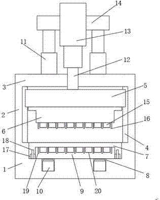
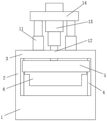
[0017] refer to Figure 1-2 , an electrical switch forming device, comprising a forming table 1, support plates 2 are fixed on both sides of the top of the forming table 1, slide rails 4 are fixed on the opposite sides of the two support plates 2, and the tops of the two support plates 2 are fixed with Top plate 3, the top both sides of top plate 3 are all fixed with the first push rod motor 11, and the top of the first push rod motor 11 is fixed with mounting plate 14, and the middle part of mounting plate 14 is equipped with the second push rod motor 13, and the second push rod motor 13 is installed on the top of the first push rod motor 11. The lower end of the ro...


PUM


Abstract

The invention discloses an appliance switch forming device. The appliance switch forming device comprises a forming table. Supporting plates are fixed to the two sides of the top of the forming table.Sliding rails are fixed to the opposite side faces of the two supporting plates. A top plate is fixed to the top of the two supporting plates. First push rod motors are fixed to the two sides of thetop of the top plate. A second push rod motor is mounted in the middle of a mounting plate. A push rod is fixed to the lower end of the second push rod motor. A sliding plate is fixed to the lower endof the push rod. Sliding blocks are arranged on the two sides of the sliding plate and slidably connected to the sliding rails. The sliding plate slides up and down on the sliding rails. An upper pressing plate is fixed to the bottom of the sliding plate through bolts. A mounting groove is formed in the top of the forming table. Storage grooves are formed in the two sides of the bottom of the mounting groove. Third push rod motors are mounted in the storage grooves. A lower pressing plate is mounted at the bottom of the mounting groove. The appliance switch forming device is reasonable in structure, unique in design, novel in structure and suitable for popularization.

Description

technical field [0001] The invention relates to the technical field of electrical switch processing, in particular to an electrical switch forming device. Background technique [0002] Switching appliances refer to switches used in low-voltage electrical appliances for infrequently manually switching on and off circuits, or as switches for introducing power in machine tool circuits. They are divided into knife switches, combination switches, etc., and are used in electrical control equipment in industrial and mining enterprises. In the electrical control equipment of industrial and mining enterprises, low-voltage electrical appliances are basically used. Therefore, low-voltage electrical appliances are the basic components in electrical control, and the quality of the control system is directly related to the performance of low-voltage electrical appliances. As an electrical engineering technician, you should be familiar with the structure, working principle and usage of lo...

Claims


Application Information

Patent Timeline
Patent Type & Authority Applications(China)
IPC IPC(8): B21D35/00B21D37/10
CPCB21D35/001B21D35/003B21D37/10
Inventor 刘开成
Owner ANHUI KAICHENG ELECTRIC APPLIANCE CO LTD
Why Eureka
Try Eureka