Dual-power-supply change-over switch

A dual power conversion and switching technology, which is applied in switchgear, pull-out switch cabinets, emergency power arrangements, etc., can solve the problems that cannot meet the requirements of important power supply places with heavy loads, difficult mechanical interlocking, and large power supply loads. Achieve the effect of reducing the difficulty of post-processing, improving the safety of use, and reasonable structure

Pending Publication Date: 2018-04-24
天津市先智电气设备有限公司
View PDF1 Cites 0 Cited by
  • Summary
  • Abstract
  • Description
  • Claims
  • Application Information

AI Technical Summary

Problems solved by technology

[0002] As the market has higher and higher requirements for the continuity of the power supply system, the known power distribution technology field, especially for important loads, generally uses dual power supplies for power supply, and dual power supply automatic replacement appliances also appear. Due to voltage insulation problems, The automatic conversion of the power supply is basically carried out on the low-voltage side of the power supply system. However, the power supply load is getting larger and larger. The current known technology, the maximum conversion current of the low-voltage dual power supply conversion appliance is 6300A, and the maximum conversion capacity is 4500KW, which can no longer meet the important requirements of large loads. According to the requirements of power supply places, high-voltage power switching has become a trend of technological development. The existing technology generally adopts two high-voltage switch cabinets, which are large in size, difficult to achieve mechanical interlocking, and have a high failure rate. Therefore, a high-voltage integrated automatic Transfer switch is very necessary

Method used


Image

  • Dual-power-supply change-over switch
  • Dual-power-supply change-over switch
  • Dual-power-supply change-over switch

Examples


Embodiment Construction

[0038] The present invention will be further described in detail below in conjunction with the drawings and specific embodiments. It should be understood that the specific embodiments described herein are only used to explain the present invention, but not to limit the present invention.

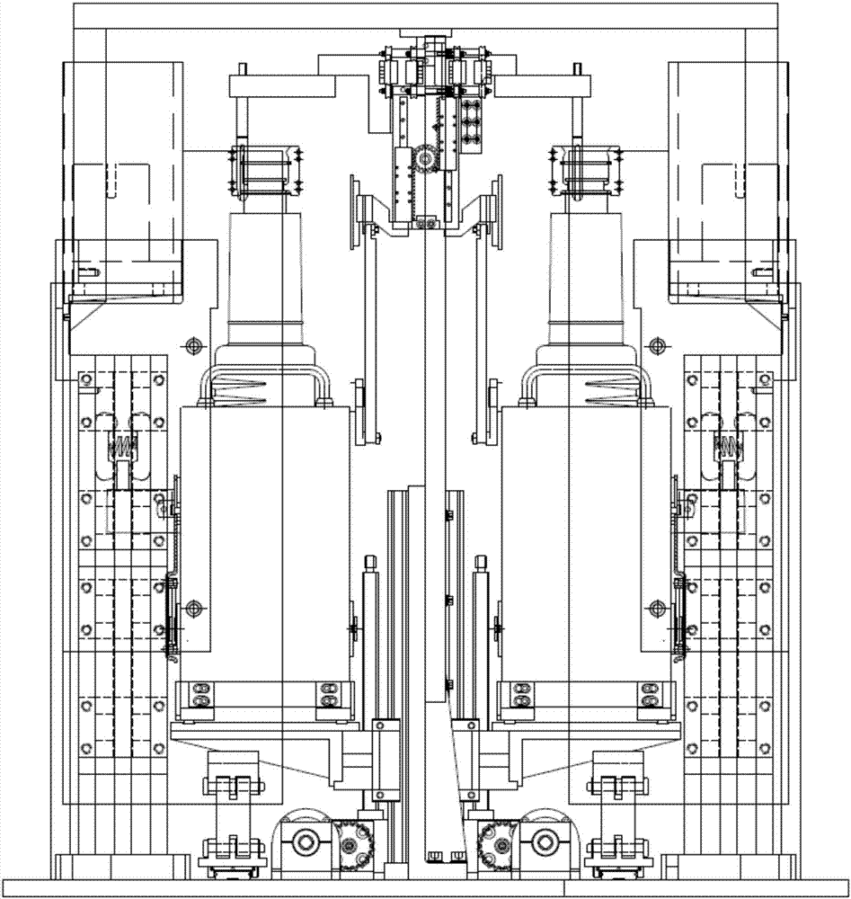
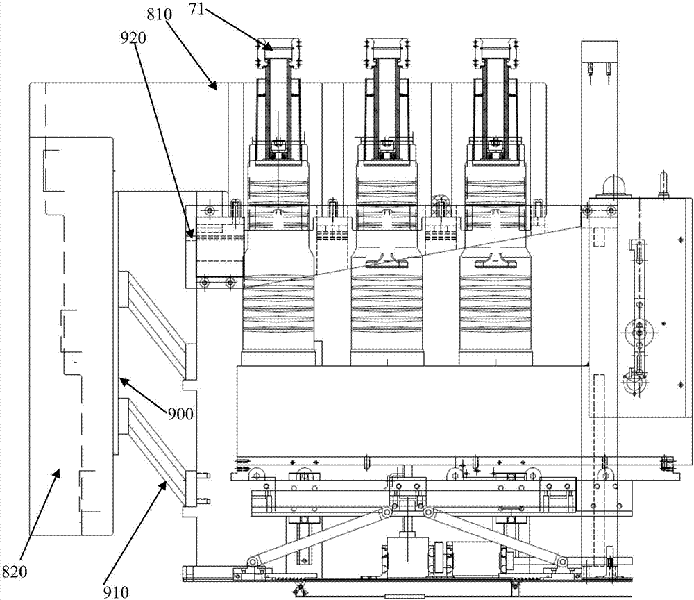
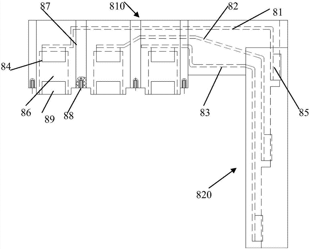
[0039] Such as Figure 1-15 As shown, a dual power transfer switch of the present invention includes a bracket 1 with a vertical beam 11 in the middle, and two busbar integrated insulated contact boxes fixedly arranged on both sides of the bracket. Two lifters are arranged on both sides of the bracket. Mechanism, a handcart provided on the pallet of the lifting mechanism and carrying multiple side-outlet poles 70 and actuators, movable opening and closing high-voltage insulated valves, and two sets of actuators for interlocking Mechanical interlocking mechanism; the busbar integrated insulated contact box includes three busbars 81, 82, 83 arranged at intervals and covered by insulators, respec...


PUM


Abstract

The invention discloses a dual-power-supply change-over switch, which comprises a bracket, two L-shaped busbar integrated insulating contact boxes, lifting mechanisms arranged on both sides of the vertical beam of the bracket, a translational driving type protection mechanism, an insulating movable door and mechanical interlocking mechanisms, wherein the bracket is provided with a vertical beam inthe middle part; the two insulating contact boxes are fixed on two sides of the top part of the bracket respectively, and a supporting mechanism of each insulating contact box comprises a stand column fixedly arranged at a bending position of the insulating contact box; and the insulating movable door comprises a front door plate and a rear door plate which are arranged in parallel and driven byracks fixedly connected with the same to move asynchronously in the same direction or translate in different directions. According to the dual-power-supply change-over switch, execution mechanisms arearranged on liftable supporting plates, the height space is fully utilized, and actuating mechanisms are simplified; by adopting the front door plate and the rear door plate which move in the same direction and are arranged in a front-back interval mode and adopting a front-back overlapping form, the design space of the movable door is effectively saved, the miniaturization of the driving mechanisms is realized, and the structure is reasonable; and through utilizing the action control on the front door plate and the rear door plate driven by a handcart to translate intermittently, corresponding through hole overlapping or staggering is realized, the safety is effectively ensured, concision is realized, and the actions are reliable.

Description

Technical field [0001] The invention relates to the technical field of dual power supply switching equipment and switch cabinets, and in particular to a dual power supply switching switch with a liftable actuator. Background technique [0002] As the market has higher and higher requirements for the continuity of the power supply system, the well-known power distribution technology fields, especially important loads, generally use dual power supplies for power supply, and dual power supplies automatically install and replace appliances. Due to voltage insulation problems, The automatic conversion of power supply is basically carried out on the low-voltage side of the power supply system. However, the power supply load is getting heavier. At present, the known technology, the maximum conversion current of low-voltage dual power conversion appliances is 6300A, and the maximum conversion capacity is 4500KW, which can no longer meet the requirements of large loads. High-voltage power...

Claims


Application Information

Patent Timeline
IPC IPC(8): H02J9/06H02B11/167H02B11/04
CPCH02B11/04H02B11/167H02J9/061H02J9/068
Inventor 王平王金杰
Owner 天津市先智电气设备有限公司
Why Eureka
Try Eureka