fly-back AC-AC converter static var compensator

A static var compensation and flyback technology, applied in reactive power adjustment/elimination/compensation, AC power input conversion to AC power output, AC network circuits, etc., can solve weak voltage matching, increase device size, Poor reliability of STATCOM devices and other issues, to achieve the effect of reducing the number of inductors and transformer windings, easy modular manufacturing, and improving reliability

Inactive Publication Date: 2018-04-24
NANJING UNIV OF SCI & TECH
View PDF2 Cites 0 Cited by
  • Summary
  • Abstract
  • Description
  • Claims
  • Application Information

AI Technical Summary

Problems solved by technology

The DC side of the voltage source inverter uses a large-capacity electrolytic capacitor bank as an energy storage element. The use of electrolytic capacitors brings the following problems: first, the electrolytic capacitor has a short life and is easily damaged, which makes the STATCOM device less reliable; second, Energy storage capacitors are bulky and expensive, which greatly limits the market prospects of STATCOM
The current research on new static var compensators is based on step-down AC-AC converters, and the research content is single. In addition, when the reactive power compensation capacitor is determined, the adjustment range of the reactive power compensation current provided by it is small, and there is also a power grid. The shortcomings of electrical isolation, weak voltage matching, and low safety and reliability between the reactive power compensation capacitor and the reactive power compensation capacitor; although there are static var compensators based on high-frequency isolated push-pull forward direct AC-AC converters, the power used The large number of switching tubes increases the volume of the device, increases the complexity of control, and is not easy to manufacture in a modular manner. Therefore, the introduction of a new type of AC-AC converter, the expansion of the reactive power compensation current adjustment range, and the realization of electrical isolation between input and output, etc. in-depth research

Method used


Image

  • fly-back AC-AC converter static var compensator
  • fly-back AC-AC converter static var compensator
  • fly-back AC-AC converter static var compensator

Examples


Embodiment 1

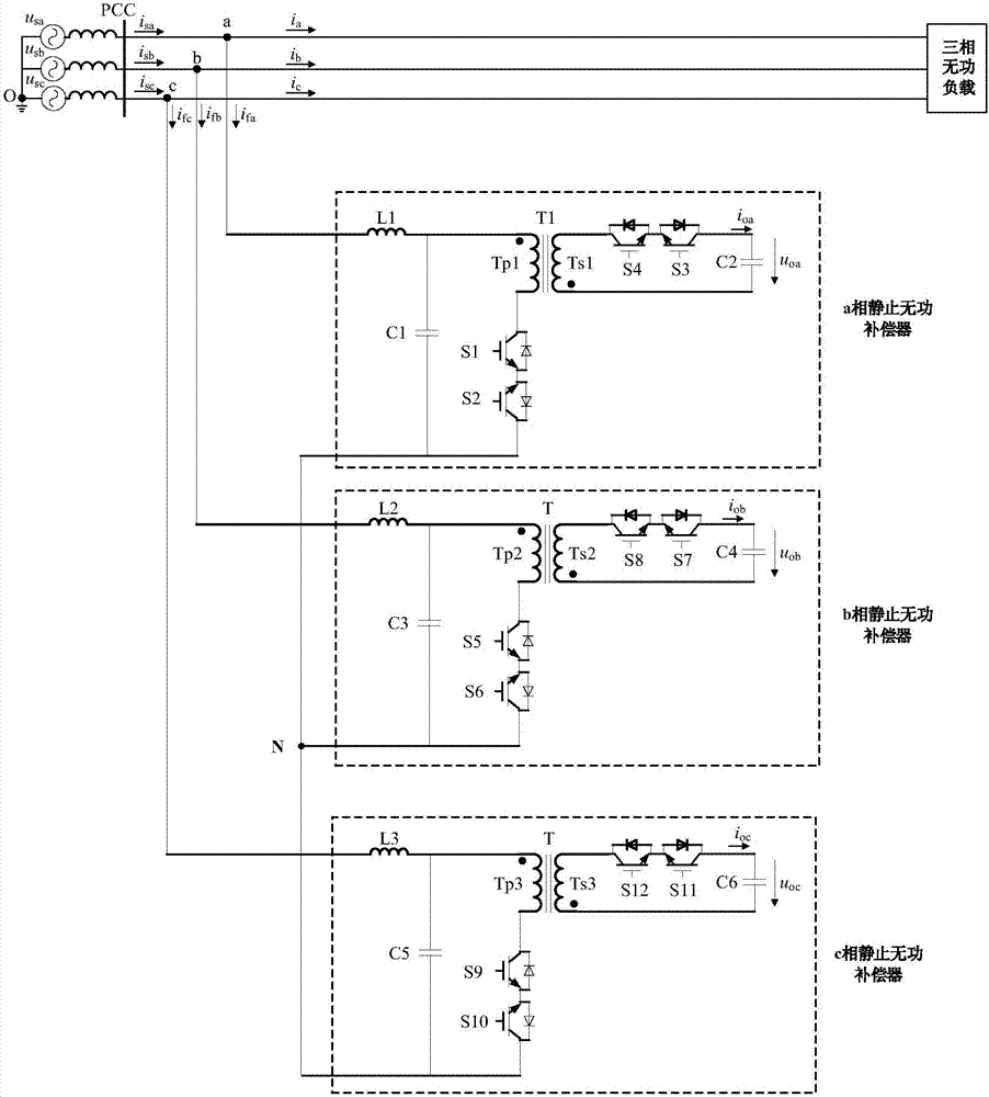
[0044] combine figure 1 As shown, a static var compensator based on a flyback AC-AC converter includes a three-phase static var compensator main power circuit, wherein each single-phase static var compensator main power circuit includes sequentially connected input filter, flyback AC-AC conversion unit and reactive power compensation capacitor. The main power circuit of the three-phase static var compensator includes the main power circuit of the a-phase static var compensator, the main power circuit of the b-phase static var compensator and the main power circuit of the c-phase static var compensator, and the main power circuit of the a-phase static var compensator One end of the main power circuit of the power compensator is connected to the transmission line between the grid side of phase a and the reactive load of phase a, and one end of the main power circuit of the static var compensator of phase b is connected to the grid side of phase b and the reactive load of phase b...


PUM


Abstract

The invention relates to the power system application technical field, and discloses a fly-back AC-AC converter static var compensator comprising three-phase static var compensator main power circuits; each single-phase static var compensator main power circuit comprises an input filter, a fly-back AC-AC conversion unit and a reactive compensation capacitor, and can make dynamic compensations forwattless current on the three-phase three-wire system power grid side. The fly-back AC-AC converter-based static var compensator does not need a large electrolytic capacitor, and uses a film capacitoras the reactive compensation capacitor; the whole device is lower in price, and modularization manufacturing can be realized; a high frequency isolation transformer can realize electrical isolation between the reactive compensation capacitor and the three-phase three-wire system power grid side, thus improving the device reliability.

Description

technical field [0001] The invention belongs to the technical field of power system application, and in particular relates to a static var compensator based on a flyback AC-AC converter. Background technique [0002] With the rapid development of the economy, reactive power has become an important physical quantity in the power system. Most network components and loads need to consume reactive power. It is obviously unreasonable for these reactive power to be provided by generators and to achieve long-distance transmission. It is even impossible, and the reasonable method is to set up reactive power compensation devices where reactive power needs to be consumed, and absorb (or send out) reactive power to the grid. [0003] The early reactive power compensation devices include synchronous condensers, shunt capacitors, etc., which have many disadvantages such as large size, high cost, and limited dynamic compensation. Therefore, static var compensation devices appeared later,...

Claims


Application Information

Patent Timeline
Patent Type & Authority Applications(China)
IPC IPC(8): H02J3/18H02M5/00
CPCH02J3/1821H02M5/00Y02E40/10
Inventor 陆佳炜李磊郭志刚李福印李广强
Owner NANJING UNIV OF SCI & TECH
Why Eureka
Try Eureka