
Barrel type refrigerant compressor

A compressor and barrel-type technology, applied in the field of refrigerant compressors, can solve the problems of single-layer layout of the unit, failure to meet high-pressure sealing, and heavy unit weight, etc., to achieve shortened procurement cycle, light weight, and low cost input Effect

Active Publication Date: 2018-04-24
SHENYANG TURBO MASCH CORP
View PDF7 Cites 3 Cited by
  • Summary
  • Abstract
  • Description
  • Claims
  • Application Information

AI Technical Summary

Problems solved by technology

MCL horizontally split refrigerant compressors have the advantages of light weight and low cost of the unit, but they cannot meet the requirements of high-pressure sealing and difficult to achieve single-layer arrangement of units; while BCL vertically split refrigerant compressors have good high-pressure sealing , A single-layer layout of the unit can be realized, but there are problems of heavy unit weight and high cost

Method used


Image

  • Barrel type refrigerant compressor
  • Barrel type refrigerant compressor
  • Barrel type refrigerant compressor

Examples


Embodiment 1

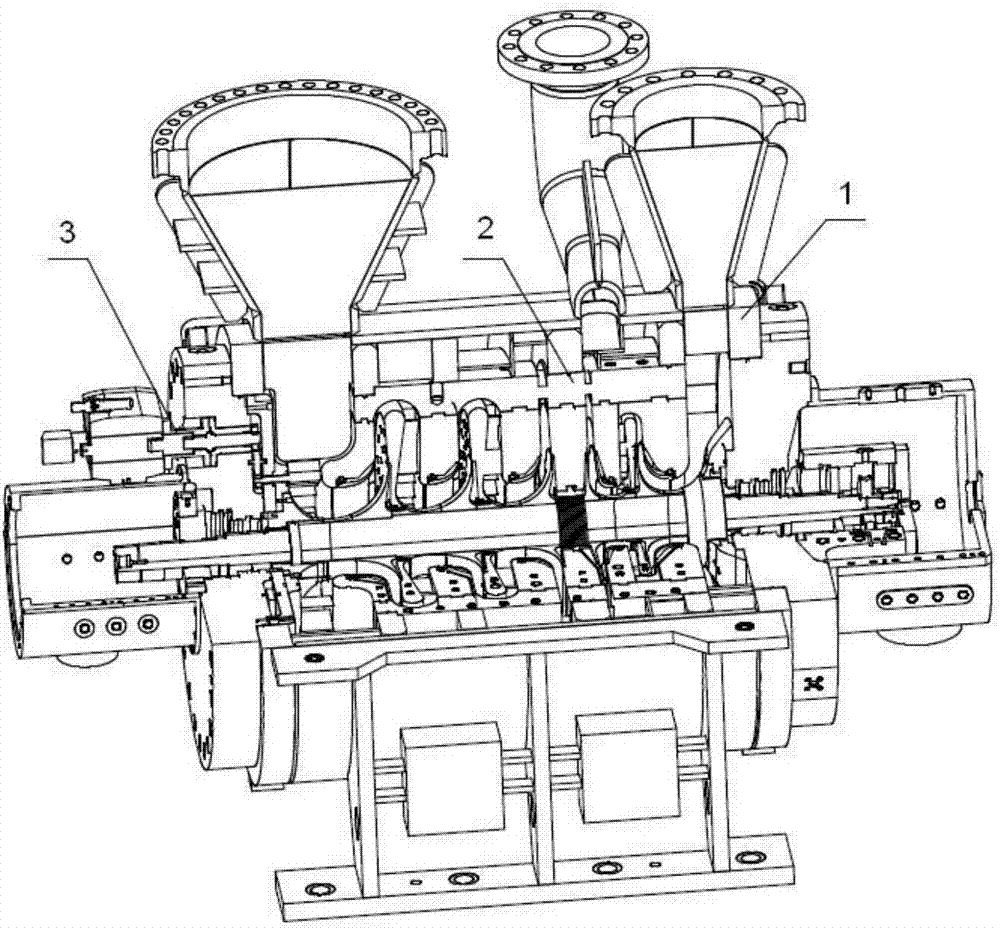
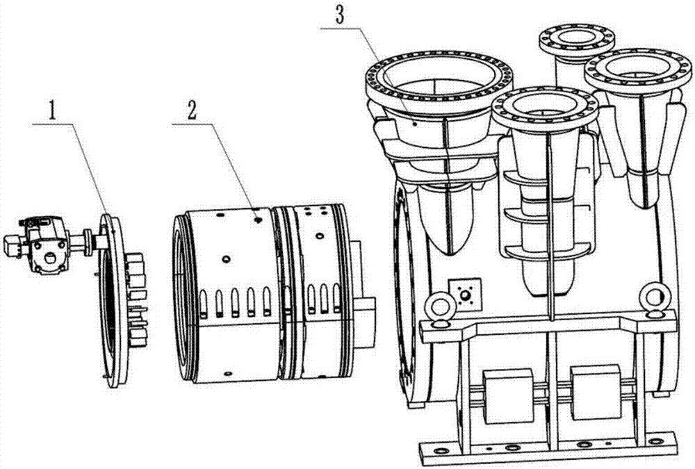
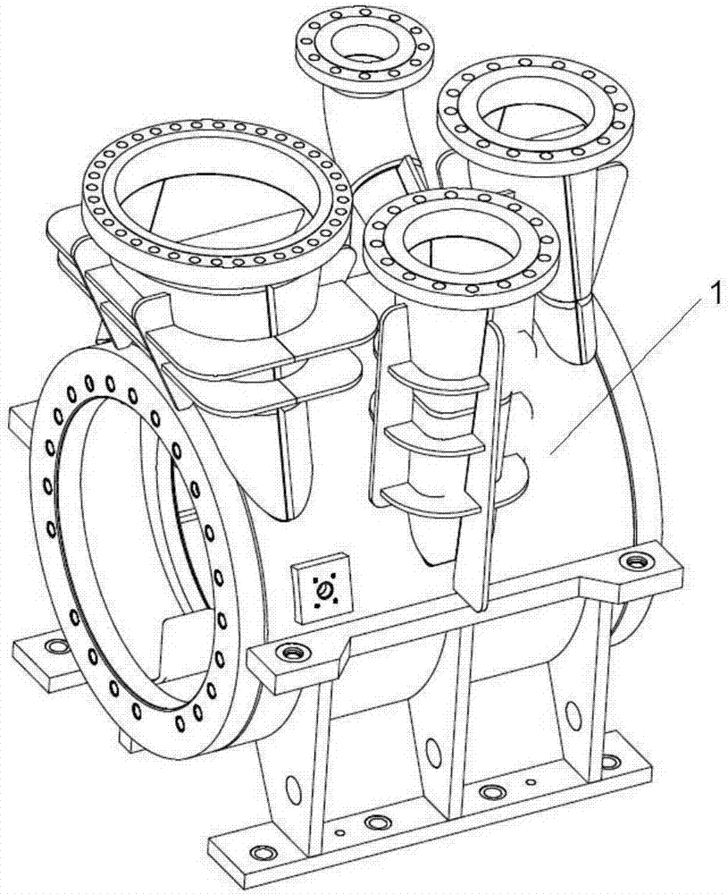
[0035] like Figures 1 to 4 As shown, the cylindrical refrigerant compressor includes a cylindrical welded casing 1, an inner casing 2 and an adjustable guide vane actuator 3. A support ring and a baffle are welded on the inner wall of the cylindrical welded casing 1, and the support ring and the baffle form a volute inside the cylindrical welding casing 1, the inner casing 2 is arranged inside the cylindrical welding casing 1, and a connecting rib group 4 is arranged along the circumferential direction of the shell wall of the inner casing 2 to connect The rib group is used to divide the inner casing 2 into at least two unit inner casings; the adjustable guide vane actuator 3 is arranged in the cylindrical welding casing 1 on the side close to the inner casing 2 .

[0036] The cylindrical welded casing 1 is welded by the Q345R plate, and the Q345R plate is composed of the following chemical composition in weight percentage: C 0.02%, Si 0.3%, Mn 1.2%, P 0.002%, S 0.015% , CaO...

Embodiment 2

[0044]Referring to Example 1, the cylindrical refrigerant compressor provided in this embodiment is different in that the cylindrical welded casing 1 is welded by the Q345R plate, and the Q345R plate consists of the following weight percentages: Chemical composition: C0.2%, Si 0.5%, Mn 1.3%, P 0.01%, S 0.01%, CaO 0.003%, Co 0.16%, Cu 0.03%, Alt 0.02%, V 0.01%, and the balance of Fe and unavoidable impurities.

Embodiment 3

[0046] Referring to Example 1, the cylindrical refrigerant compressor provided in this embodiment is different in that the cylindrical welded casing 1 is welded by the Q345R plate, and the Q345R plate consists of the following weight percentages: Chemical composition: C0.1%, Si 0.2%, Mn 1.6%, P 0.02%, S 0.013%, CaO 0.0025%, Ni 0.4%, Co 0.18%, Cu0.2%, Al t 0.01%, V 0.025% , and the balance of Fe and unavoidable impurities.


PUM


Abstract

The invention relates to a barrel type refrigerant compressor. The compressor comprises a barrel type welding machine shell, an inner machine shell and an adjustable guide blade execution mechanism, wherein a volute chamber is arranged inside the barrel type welding machine shell; the inner machine shell is arranged inside the barrel type welding machine shell, and a connecting rib set is arrangedin the circumferential direction of the shell wall of the inner machine shell and is used for dividing the inner machine frame into at least two units of inner machine frame bodies; and the inner machine shell is arranged in the part, close to one side of the inner machine shell, of the barrel type welding machine shell. The barrel type refrigerant compressor has the advantages of being light inunit weight and low in unit cost, and the refrigerant compressor can also achieve high-pressure sealing performance and the single-layer arrangement of the unit.

Description

technical field [0001] The invention relates to the technical field of refrigerant compressors, in particular to a cylindrical refrigerant compressor. Background technique [0002] At present, refrigerant compressors are mainly divided into two types, namely MCL horizontal split refrigerant compressors and BCL vertical split refrigerant compressors. MCL horizontally split refrigerant compressors have the advantages of light weight and low cost of the unit, but they cannot meet the requirements of high-pressure sealing and difficult to achieve single-layer arrangement of units; while BCL vertically split refrigerant compressors have good high-pressure sealing 1. The single-layer arrangement of the unit can be realized, but there are problems of heavy unit weight and high cost. Contents of the invention [0003] Aiming at the shortcomings of the above-mentioned prior art, the present invention provides a cylindrical refrigerant compressor. [0004] The purpose of the prese...

Claims


Application Information

Patent Timeline
Patent Type & Authority Applications(China)
IPC IPC(8): F04D29/42F04D29/46F04D29/02C22C38/02C22C38/04C22C38/10C22C38/08C22C38/16C22C38/06C22C38/12C22C33/04
CPCF04D29/023F04D29/4226F04D29/462C22C33/04C22C38/02C22C38/04C22C38/06C22C38/105C22C38/12C22C38/16F04D17/122
Inventor 李寅杰韩亮王玉旌曲岳坤张弛董浩富英楠
Owner SHENYANG TURBO MASCH CORP
Learn More