Machine detachment device and machine detachment system
A release device and mechanical technology, applied in the field of medical devices, can solve the problems of affecting the operation time, reducing the controllability of the spring coil, and long release time, etc., and achieve the effect of strong controllability and guaranteed controllability
- Summary
- Abstract
- Description
- Claims
- Application Information
AI Technical Summary
Problems solved by technology
Method used
Image

Examples
no. 1 example
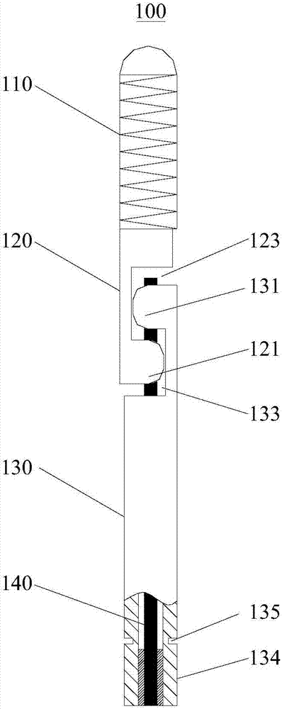
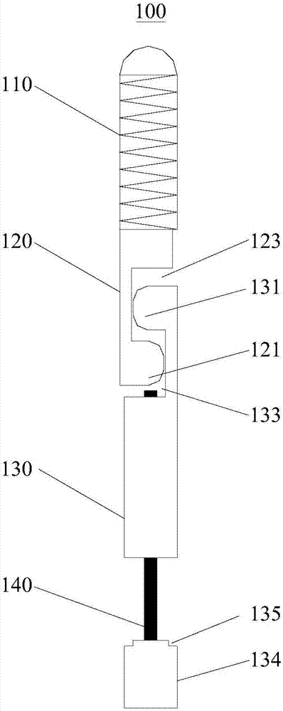
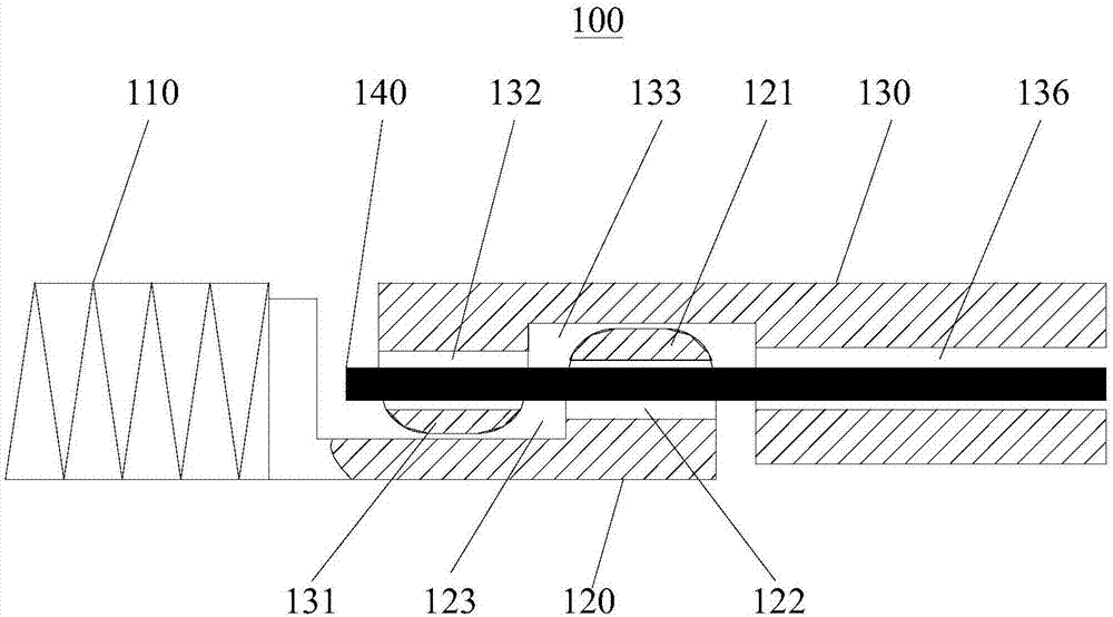
[0035] Please refer to Figure 1 to Figure 3As shown, the present embodiment provides a mechanical release device 100 for an embolism coil, which includes a coil 110 , a release connector 120 , a push rod 130 and a core wire 140 . The spring coil 110 is fixed on one end of the release connector 120, and one end of the push rod 130 is a breakable end 134, and the other end cooperates with the end of the release connector 120 away from the spring ring 110, and the core wire 140 is coaxially inserted into the push rod 130 Inside, one end of the core wire 140 is fixedly connected to the broken end 134 , and the other end runs through the matching end of the release connector 120 and the push rod 130 , and the broken broken end 134 can drive the core wire 140 to be pulled out. Specifically, the push rod 130 is provided with a coaxial rod body hole 136, and the core wire 140 is arranged in the rod body hole 136. The rod body hole 136 is generally a through hole, and can also be a bl...
no. 2 example
[0045] Please refer to Figure 4 As shown, this embodiment provides a mechanical release device 200 for an embolism coil, the structure of which is roughly the same as that of the mechanical release device 100 in the first embodiment, except that the first protrusion in this embodiment The portion 221 and the first recessed portion 223 are an integral part, but not limited thereto; the second protrusion 231 , the second recessed part 233 and the push rod 230 are integral parts, but not limited thereto. The side of the first protruding portion 221 close to the first concave portion 223 and the side of the second protruding portion 231 close to the second concave portion 233 are slopes that are inclined toward the broken end 134 relative to the core wire 140, and the two slopes can be completely attached to each other. combine.
[0046] see image 3 , Figure 4 and Figure 7 As shown, the clinical application method of the mechanical release device 200 is:
[0047] The mech...
no. 3 example
[0051] Please refer to Figure 5 As shown, this embodiment provides a mechanical release device 300 for an embolism coil, the structure of which is roughly the same as that of the mechanical release device 100 in the first embodiment, except that the first protrusion in this embodiment The portion 321 and the first recessed portion 323 are an integral part, but not limited thereto; the second protrusion 331 , the second recessed part 333 and the push rod 330 are integral parts, but not limited thereto. The side of the first protruding portion 321 close to the first concave portion 323 and the side of the second protruding portion 331 close to the second concave portion 333 are slopes that are inclined toward the coil 110 relative to the core wire 140 , and the two slopes can be completely attached to each other. combine.
[0052] see image 3 , Figure 5 and Figure 7 As shown, the clinical application method of the mechanical release device 300 is:
[0053] The mechanica...
PUM
 Abstract
Description
Claims
Application Information
 - Generate Ideas
- Intellectual Property
- Life Sciences
- Materials
- Tech Scout
- Unparalleled Data Quality
- Higher Quality Content
- 60% Fewer Hallucinations
Browse by: Latest US Patents, China's latest patents, Technical Efficacy Thesaurus, Application Domain, Technology Topic, Popular Technical Reports.
© 2025 PatSnap. All rights reserved.Legal|Privacy policy|Modern Slavery Act Transparency Statement|Sitemap|About US| Contact US: help@patsnap.com