IoT signal status indication circuit for IoT home appliances
A technology for indicating circuit and signal status, applied in electrical components, data exchange networks, home automation networks, etc., can solve problems such as difficult to completely filter out clutter, inaccurate IoT signal detection, large error in IoT signal status indication, etc.
- Summary
- Abstract
- Description
- Claims
- Application Information
AI Technical Summary
Problems solved by technology
Method used
Image
Examples
Embodiment 1
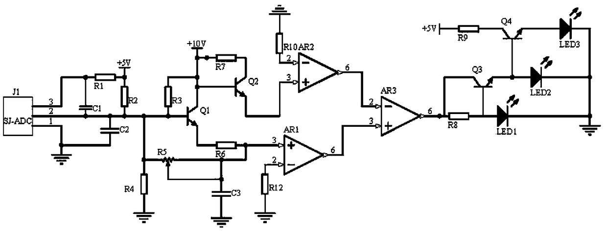
[0014] Embodiment 1, the signal state indication circuit of the Internet of Things home appliances, including a frequency acquisition circuit, a frequency modulation circuit, a comparison amplifier circuit and an indication circuit, the frequency acquisition circuit collects the frequency of the Internet of Things signal when the Internet of Things function of the Internet of Things home appliance is used , the frequency modulation loop selects the frequency of the frequency signal by using a composite circuit composed of transistors Q1, Q2, capacitor C3 and adjustable resistor R5, and filters out the clutter in the frequency signal, wherein the frequency modulation can be adjusted by adjusting the resistance of the adjustable resistor R5 The potential size of the loop output signal, the output signal of the frequency modulation loop is compared and amplified by the comparison amplifier circuit using the operational amplifier AR1 and AR2 respectively input to the non-inverting i...
Embodiment 2
[0016] Embodiment 2. On the basis of Embodiment 1, the frequency acquisition circuit selects the frequency collector J1 of the model SJ-ADC to collect the frequency of the Internet of Things signal when the Internet of Things home appliance is used and outputs an analog potential signal. Capacitor C2 It is a filter capacitor, the power supply terminal of the frequency collector J1 is connected to one end of the resistor R1 and one end of the capacitor C1, the other end of the resistor R1 is connected to the power supply +5V and one end of the resistor R2, and the output terminal of the frequency collector J1 is connected to the other end of the capacitor C1 , one end of the capacitor C2, the other end of the resistor R2 and the base of the transistor Q1, the ground end of the frequency collector J1 and the other end of the capacitor C2 are grounded.
Embodiment 3
[0017]Embodiment 3. On the basis of Embodiment 1, the indication circuit uses triodes Q3 and Q4 to form a step-by-step conduction circuit. When the signal input by the frequency acquisition circuit is between +8V-+10V, the triodes Q3 and Q4 are both When it is turned on, the indicators LED1-LED3 are all on at this time, which means that the IoT signal needs to be repaired and the IoT home appliance needs to be shut down immediately when the IoT appliance is in use, which is a three-level alarm; when the signal input by the frequency acquisition circuit is at +7V When between -+8V, the triode Q3 is turned on, and the indicators LED1 and LED2 are on at this time, which means that the IoT signal of the IoT home appliance needs to be repaired when the IoT is in use, and the IoT home appliance does not need to be turned off, which is a secondary alarm; when the frequency is collected When the signal input by the circuit is between +5V-+7V, the indicator LED1 is on at this time, whic...
PUM
 Abstract
Description
Claims
Application Information
 - R&D
- Intellectual Property
- Life Sciences
- Materials
- Tech Scout
- Unparalleled Data Quality
- Higher Quality Content
- 60% Fewer Hallucinations
Browse by: Latest US Patents, China's latest patents, Technical Efficacy Thesaurus, Application Domain, Technology Topic, Popular Technical Reports.
© 2025 PatSnap. All rights reserved.Legal|Privacy policy|Modern Slavery Act Transparency Statement|Sitemap|About US| Contact US: help@patsnap.com


