
Arc extinguishing chamber for miniature circuit breaker

A technology for small circuit breakers and arc extinguishing chambers, which is applied to circuit breaker parts and other directions, can solve the problems of reducing the dielectric strength of arc extinguishing chambers, not conforming to the use of small circuit breakers, and the overall structure of arc extinguishing chambers is complex. Arc extension effect, convenient and quick assembly, and the effect of enhancing work stability

Pending Publication Date: 2018-04-20
GACIA ELECTRICAL APPLIANCE
View PDF1 Cites 0 Cited by
  • Summary
  • Abstract
  • Description
  • Claims
  • Application Information

AI Technical Summary

Problems solved by technology

However, the overall structure of the arc extinguishing chamber is relatively complicated, which is not suitable for the use of small circuit breakers, and because the air holes on the arc extinguishing plate are straight-through design, the force generated by the induced magnetic field of the free grid may be ejected from the arc injection port When the arc is pulled back into the arc extinguishing chamber, the metal particles contained in the arc free steam will return to the arc extinguishing chamber, thereby relatively increasing the density of metal vapor in the arc extinguishing chamber; in addition, the size of the hole on the arc extinguishing plate and the discharge The cloth is adapted to the grid interval, which is more conducive to the return of metal particles in the arc free steam to the arc extinguishing chamber, thereby reducing the dielectric strength of the arc extinguishing chamber

Method used


Image

  • Arc extinguishing chamber for miniature circuit breaker
  • Arc extinguishing chamber for miniature circuit breaker
  • Arc extinguishing chamber for miniature circuit breaker

Examples


Embodiment Construction

[0025] The present invention will now be described in further detail in conjunction with the accompanying drawings.

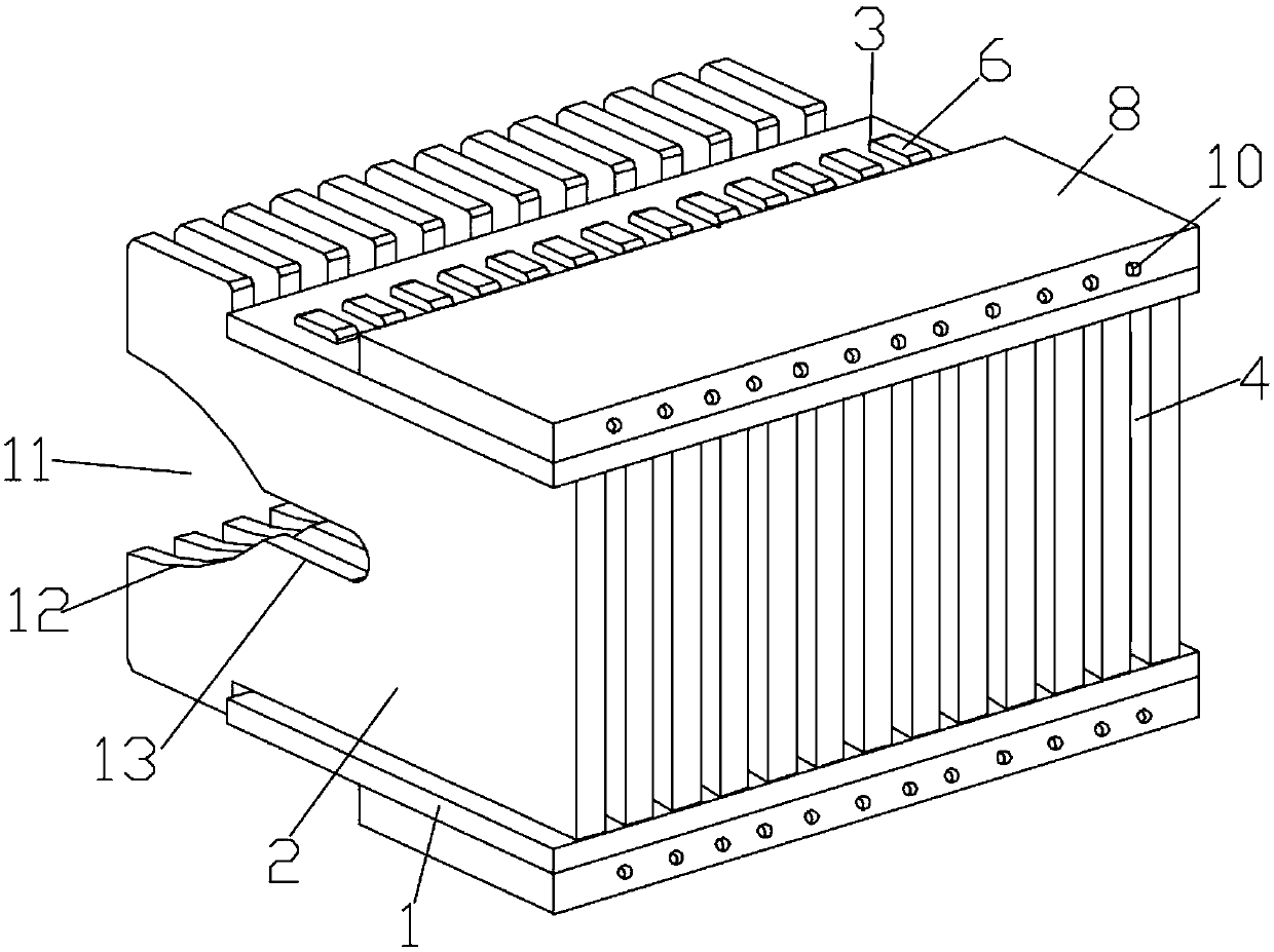
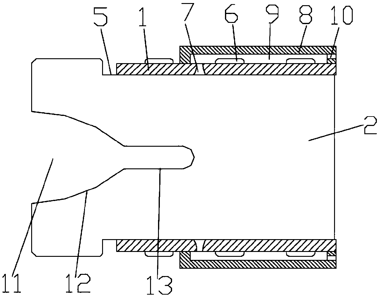
[0026] like figure 1 As shown, an arc extinguishing chamber for a small circuit breaker includes two parallel and symmetrically arranged fixed plates 1 and several parallel arc extinguishing grids 2 arranged between the two fixed plates 1, and the fixed plates 1 are There are several groups of fixing mechanisms evenly distributed along the length direction of the fixing plate 1, and the fixing mechanisms include three fixing holes 3 evenly distributed along the width direction of the fixing plate 1. In practical applications, the number of fixing holes 3 can be Select according to actual needs, the arc extinguishing grid 2 includes an air inlet end, an air outlet and two opposite side ends, and the two sides of the air outlet on the arc extinguishing grid 2 are respectively outwardly expanding arcs Shaped structure, so that an inwardly shrinking gas outlet cha...


PUM


Abstract

The invention discloses an arc extinguishing chamber for a miniature circuit breaker. The arc extinguishing chamber comprises two fixed plates and a plurality of arc extinguishing grid sheets arrangedbetween the two fixed plates, a plurality of groups of fixing mechanisms are uniformly distributed on the fixed plates, the fixing mechanism comprises a plurality of fixing holes, and the arc extinguishing grid sheet comprises an inlet end, an outlet end and two side ends, wherein the two sides of the outlet end of the arc extinguishing grid sheet are respectively arc-shaped structures expanded outward; an outlet channel contracted inward is formed between the outlet ends of the two adjacent arc extinguishing grid sheets; each of the two side ends of the arc extinguishing grid sheet is provided with a fixed right angle on the side near the outlet end, a fixed block matched with the fixing hole is arranged corresponding to the fixing hole on the fixed right angle, and one end of the fixedblock penetrates the corresponding fixing hole. The arc extinguishing chamber is reasonable in structure design and convenient and fast to install, can effectively avoid the phenomenon that metal particles in arc free steam easily return to the arc extinguishing chamber, and can effectively improve the arc cooling rate at the same time.

Description

technical field [0001] The invention relates to the technical field of circuit breakers, in particular to an arc extinguishing chamber for a small circuit breaker. Background technique [0002] Arc is a kind of gas discharge phenomenon, which is the instantaneous spark generated by the current passing through a certain medium (such as air). In daily life, when the passing current exceeds the limit value set by the circuit breaker, the circuit breaker will automatically interrupt the current. After the contacts on the circuit breaker are disconnected, the arc will be ignited. Equipment lines cause damage, and even affect personal safety. Therefore, arc extinguishing is one of the important applications of circuit breakers. At present, arc extinguishing methods commonly used in the prior art include a mechanical arc extinguishing method, a magnetic blowing arc extinguishing method, a narrow slit arc extinguishing method and a grid arc extinguishing method. [0003] Among th...

Claims


Application Information

Patent Timeline
IPC IPC(8): H01H73/18
CPCH01H73/18
Inventor 张新雨盛勇兵黄佳
Owner GACIA ELECTRICAL APPLIANCE
Learn More