Position locking structure for mechanical installation

A locking and mechanical technology, applied in mechanical equipment, fixtures and other directions, can solve the problems of increasing structural weight and external dimensions, limitations of applicability and practicability, inconvenient disassembly and assembly, and achieves good practicability and good use stability. , the effect of reducing weight

Inactive Publication Date: 2018-04-20
临海市锐特恩电气有限公司
View PDF6 Cites 3 Cited by
  • Summary
  • Abstract
  • Description
  • Claims
  • Application Information

AI Technical Summary

Problems solved by technology

[0002] When the mechanical structure is connected, most of them are locked from the bottom up, that is, the two connecting parts are connected in layers, which increases the weight and overall size of the structure. Although it can realize the locking operation, it requires The space is large, and disassembly is extremely inconvenient, so the applicability and practicality are limited

Method used


Image

  • Position locking structure for mechanical installation

Examples


Embodiment 1

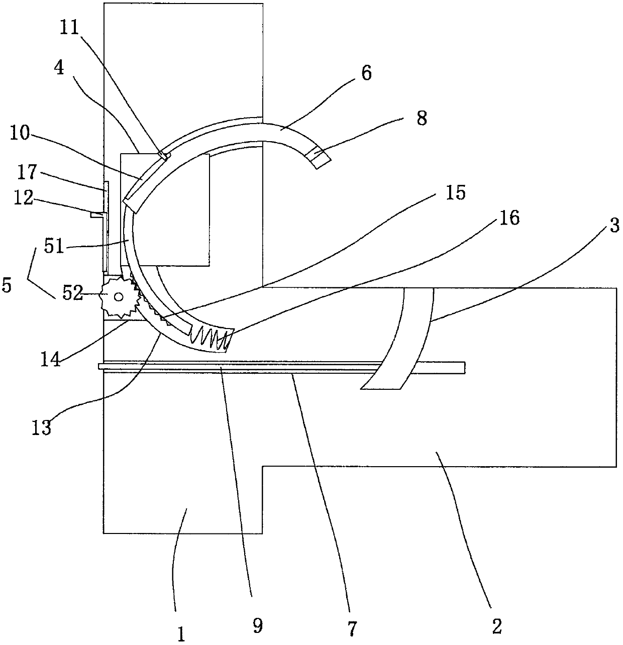
[0014] figure 1 A specific embodiment of the invention is shown in which figure 1 It is a structural schematic diagram of the present invention.

[0015] See figure 1 , a locking structure for mechanical installation, including a locking seat 1, on which a transverse bearing protrusion 2 is integrally formed, at the connection between the locking seat 1 and the transverse bearing protrusion 2 An arc-shaped locking hole 3 is provided, a locking cavity 4 is arranged in the locking seat 1, a lifting structure 5 is fixed in the locking cavity 4, and a lifting structure 5 is fixed in the locking hole 3. An arc-shaped locking rod 6, one end of which is fixed on the lifting structure 5, and an insertion slot 7 is arranged between the locking seat 1 and the lateral bearing protrusion 2, An insertion card 9 is arranged in the insertion groove, and the insertion groove extends to the arc-shaped locking hole of the lateral bearing protrusion, and the end of the arc-shaped locking rod ...


PUM


Abstract

The invention discloses a position locking structure for mechanical installation. The position locking structure comprises a position locking seat, the position locking seat is provided with a horizontal bearing embossment in an integrated molding manner, the joint of the position locking seat and the horizontal bearing embossment is provided with an arc-shaped position locking hole, the positionlocking seat is internally provided with a position locking cavity, the position locking cavity is internally and fixedly provided with a lifting structure, the arc-shaped position locking hole is internally provided with an arc-shaped position locking rod, one end of the arc-shaped position locking rod is fixed on the lifting structure, an insert position groove is arranged between the position locking seat and the horizontal bearing embossment, the insert position groove is internally provided with a inserting-clamping piece, the insert position groove extends to the arc-shaped position locking hole of the horizontal bearing embossment, the end portion of the arc-shaped position locking rod is provided with a clamping groove, and the arc-shaped position locking rod is inserted into the arc-shaped position locking hole of the horizontal bearing embossment and is fixed by the inserting-clamping piece. The position locking structure for the mechanical installation is reasonable in structural arrangement and can be used in a narrow space, and the weight of the structure can be effectively reduced, disassembling and installing operations performed on a mechanical structure can be effectively and rapidly realized, and the position locking structure for the mechanical installation is good in use stability, high in applicability and good in practicability.

Description

technical field [0001] The invention belongs to the technical field of mechanical installation, and in particular relates to a mechanical installation locking structure. Background technique [0002] When the mechanical structure is connected, most of them are locked from the bottom up, that is, the two connecting parts are connected in layers, which increases the weight and overall size of the structure. Although it can realize the locking operation, it requires The space is large, and disassembly is extremely inconvenient, so the applicability and practicality are limited. Contents of the invention [0003] The purpose of the present invention is to provide a mechanically installed locking structure with reasonable structure and good stability in use. [0004] The technical solution to achieve the purpose of the present invention is a mechanically installed locking structure, including a locking seat, on which a lateral bearing protrusion is integrally formed, and betwe...

Claims


Application Information

Patent Timeline
Patent Type & Authority Applications(China)
IPC IPC(8): F16B1/04
CPCF16B1/04F16B2200/81
Inventor 周海兵
Owner 临海市锐特恩电气有限公司
Why Eureka
Try Eureka