
Integrated-type steel structure roof photovoltaic system

A photovoltaic system and steel structure technology, applied in the field of solar photovoltaics, can solve problems such as loose joints of photovoltaic panels and sliding of photovoltaic panels, and achieve the effects of improving roof drainage, saving materials, and optimizing structural forms

Pending Publication Date: 2018-04-20
ZHEJIANG JINGGONG ENERGY TECH GRP CO LTD
View PDF5 Cites 6 Cited by
  • Summary
  • Abstract
  • Description
  • Claims
  • Application Information

AI Technical Summary

Problems solved by technology

The disadvantage of this structure is that screws are used to penetrate the inner wall of the W-shaped bracket and connect with the roof purlins. During use, the water in the bracket will enter the building along the gap at the screw hole, resulting in water leakage.
In addition, during the 25-year operation period of the photovoltaic power station, the aging of the rubber block at the bottom will loosen the joints of the photovoltaic panels, causing the photovoltaic panels to slip

Method used


Image

  • Integrated-type steel structure roof photovoltaic system
  • Integrated-type steel structure roof photovoltaic system
  • Integrated-type steel structure roof photovoltaic system

Examples


Embodiment Construction

[0022] The present invention will be further described below in conjunction with the examples. The description of the following examples is provided only to aid the understanding of the present invention. It should be pointed out that for those skilled in the art, without departing from the principles of the present invention, some improvements and modifications can be made to the present invention, and these improvements and modifications also fall within the protection scope of the claims of the present invention.

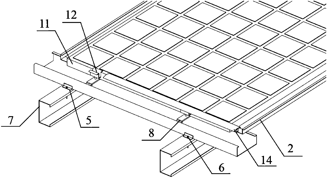
[0023] The integrated steel structure roof photovoltaic system includes main beam 1, secondary beam 2, main beam shoulder 3, semicircular notch 4, angle steel 5, first screw 6, purlin 7, support block 8, bolt hole 9, Electric welding 10, component frame 11, pressure block 12, bolt 13, bead 14, card cover 15, card foot 16, hook 17, sealant 18, waterproof tape 19, color steel tile 20, side cover plate 21, edge 22 , the second screw 23 and the photovoltaic panel. ...


PUM


Abstract

The invention relates to an integrated-type steel structure roof photovoltaic system. The integrated-type steel structure roof photovoltaic system comprises main beams, secondary beams, pieces of angle steel, purlines, supporting blocks, electric weld pieces, assembly frames, pressing blocks, pressing strips, sealants, waterproof adhesive tapes, color steel tiles, lateral cover plates and photovoltaic plates. The secondary beams are vertically erected on the two sides of the main beams correspondingly, the main beams are each in a U shape, and the two sides of the main beams are provided withmain beam shoulders, wherein the directions of the main beam shoulders are inward. Semicircular notches are pressed in the main beam shoulders, and the pieces of angle steel are welded to the outer sides of the bottoms of the main beams correspondingly and connected with the purlines through first screws. The integrated-type steel structure roof photovoltaic system has the beneficial effects thatthe main beams with the U-shaped sections, the inverted-T-shaped supporting blocks and certain compression components are adopted to constitute the integral mounting system, on-site construction is easy and convenient, materials are saved, and the roof water discharge is also greatly increased; and compared with a traditional building photovoltaic integrated system, the main beams are fixed to thepurlines through the pieces of angle steel on the outer side, inner cavities of the main beams do not need to be punched through, and water in the main beams is prevented from entering a building.

Description

technical field [0001] The invention belongs to the field of solar photovoltaic technology, and in particular relates to an integrated steel structure roof photovoltaic system. Background technique [0002] Distributed roof photovoltaic power plants have the advantages of not occupying land, not limited by photovoltaic indicators, and low cost, and have been widely used. To build a photovoltaic power station on a steel structure roof, the photovoltaic panel is often erected directly on the color steel tile, which is simple in construction and low in cost. However, the service life of conventional color steel tiles often does not meet the requirements of 25 years of photovoltaic power plant operation, or the roof color steel tiles have been corroded at the beginning of the construction of photovoltaic power plants, and the color steel tile roof needs to be replaced, which increases the investment cost of photovoltaic power plants and limits Distributed roof photovoltaic powe...

Claims


Application Information

Patent Timeline
Patent Type & Authority Applications(China)
IPC IPC(8): E04D13/00E04D13/04E04D13/18H02S20/26
CPCH02S20/26E04D13/00E04D13/04Y02E10/50Y02B10/10
Inventor 秦良忠张双燕苏森良
Owner ZHEJIANG JINGGONG ENERGY TECH GRP CO LTD
Learn More