Gantry crane rolling wheel locking device

A locking device, gantry crane technology, applied in the directions of transportation and packaging, load hanging components, walking mechanisms, etc., can solve the problems of increasing the operating cost of the gantry crane, inconvenient operation, shortening the service life of the rollers, etc., to save frequent replacement costs, The effect of avoiding safety hazards and prolonging service life

Pending Publication Date: 2018-04-20
无锡翔煌电气有限公司
View PDF0 Cites 0 Cited by
  • Summary
  • Abstract
  • Description
  • Claims
  • Application Information

AI Technical Summary

Problems solved by technology

[0003] The prior art gantry crane roller locking device has the following problems: 1. At present, the gantry crane roller locking device mostly realizes the locking function by punching holes at both ends of the roller and inserting locking pins. Pull out the locking pin to unlock, and you need to insert the locking pin to lock when transporting to the destination. The operation is extremely inconvenient and time-consuming, because it is difficult to guarantee the insertion depth of the manual pin, and sometimes the stability of the gantry crane is not stable due to improper operation by the staff. 2. Gantry cranes are mostly used in factories, ports and other fields. The environment is harsh and the ground is sandy. It is easy to cause damage to the internal structure of the rollers and shorten the service life of the rollers. Frequent replacement is required. The current roller lock Most of the locking devices are integrated with the rollers. When the rollers are replaced, the entire roller locking device needs to be replaced, which increases the operating cost of the gantry crane.

Method used


Image

  • Gantry crane rolling wheel locking device
  • Gantry crane rolling wheel locking device
  • Gantry crane rolling wheel locking device

Examples


Embodiment Construction

[0021] The following will clearly and completely describe the technical solutions in the embodiments of the present invention with reference to the accompanying drawings in the embodiments of the present invention. Obviously, the described embodiments are only some, not all, embodiments of the present invention. Based on the embodiments of the present invention, all other embodiments obtained by persons of ordinary skill in the art without making creative efforts belong to the protection scope of the present invention.

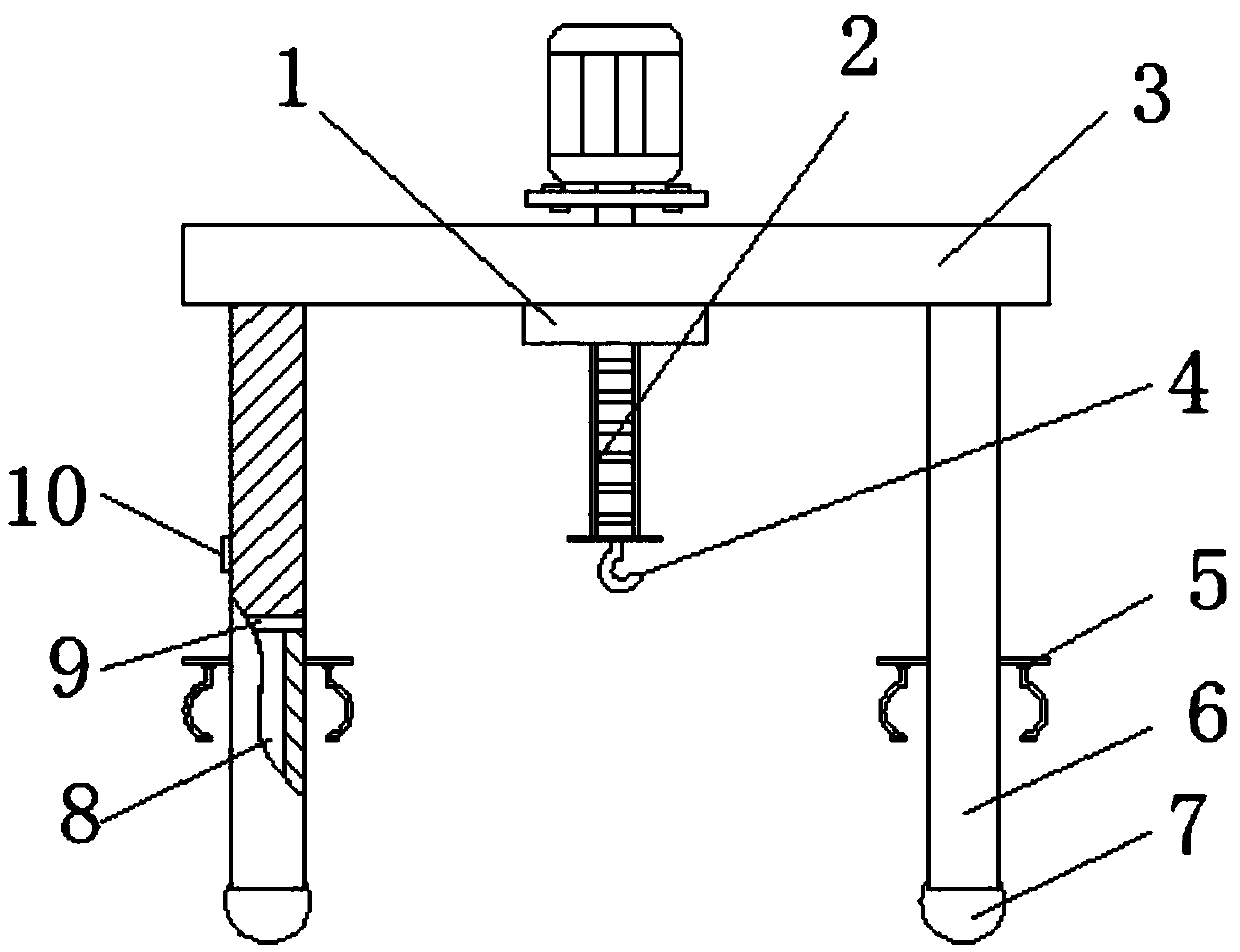
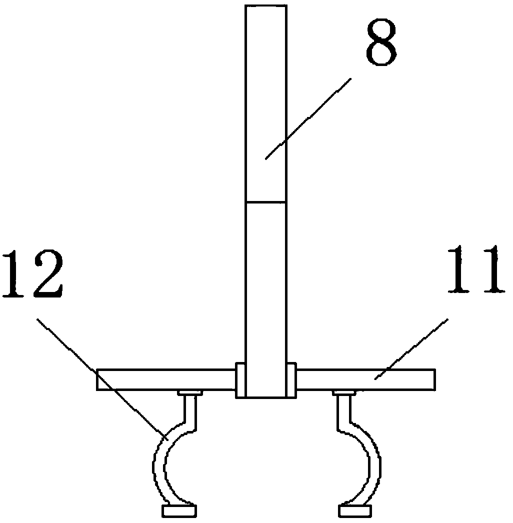
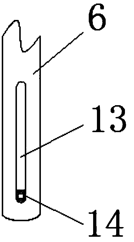
[0022] see Figure 1-6 , the present invention provides the following technical solutions: a gantry crane roller locking device, including a crossbeam 3, a moving plate 11 and a roller fixing block 12, a moving wheel set 1 is arranged in the middle of the crossbeam 3, and the left and right sides of the crossbeam 3 are respectively symmetrical A bracket 6 is provided, and the bracket 6 is divided into two parts, the upper part is solid, and the lower part is h...


PUM


Abstract

The invention discloses a roller locking device for a gantry crane, which comprises a crossbeam, a moving plate and a roller fixing block. A moving wheel set is arranged in the middle of the crossbeam, and brackets are respectively symmetrically arranged on the left and right sides of the crossbeam. The moving wheel A transmission chain is provided on the side of the group away from the beam, a hook is provided on the side of the transmission chain away from the moving wheel group, a switch is provided on the side of the bracket away from the hook, and slide rails are provided on both sides of the bracket. The present invention realizes the lifting function of the two semi-circular roller fixed blocks through the first electric telescopic column and the moving plate; the second electric telescopic column and the slider realize the contraction function of the two semi-circular roller fixed blocks; the combination of the two functions is To achieve the fixed performance of the roller, the rubber layer on the surface of the roller fixed block increases the resistance between the fixed block and the roller, the fixation is strengthened, and the whole process of mechanized operation avoids the safety hazard caused by human error operation.

Description

technical field [0001] The invention belongs to the technical field of mechanical engineering, and in particular relates to a locking device for rollers of a gantry crane. Background technique [0002] The gantry crane is a machine used to lift, transport and install materials. It is closely related to our life. It can reduce physical labor, improve work efficiency, and achieve safe production. The traditional and important auxiliary machinery, and the gantry crane is used in the factory It has been widely used in many fields such as ports, construction sites, etc. With the increasing scale of production, especially the requirements of modernization and specialized production, various special-purpose gantry cranes have been produced one after another. In many important departments, it has been It is not only an auxiliary machinery in the production process, but its development plays a positive role in promoting the construction of the national economy. The roller locking dev...

Claims


Application Information

Patent Timeline
Patent Type & Authority Applications(China)
IPC IPC(8): B66C9/18
CPCB66C9/18
Inventor 倪紫翔
Owner 无锡翔煌电气有限公司
Why Eureka
Try Eureka