Screwing tool and tool holder comprising a subdivided support section

A technology of support area and support area, which is applied to the accessories of tool holders, milling cutters, manufacturing tools, etc., can solve problems such as fracture, achieve the effects of reducing friction loss, preventing overload, and improving vibration attenuation/vibration reduction

Active Publication Date: 2018-04-17
FRANZ HAIMER MASCHINENBAU KG
View PDF6 Cites 0 Cited by
  • Summary
  • Abstract
  • Description
  • Claims
  • Application Information

AI Technical Summary

Problems solved by technology

[0003] In screw-in tools of this type, there is in principle a risk of fracture due to the very hard and brittle material, especially when too high a screw-in torque is used when assembling the screw-in tool in the tool holder

Method used


Image

  • Screwing tool and tool holder comprising a subdivided support section
  • Screwing tool and tool holder comprising a subdivided support section
  • Screwing tool and tool holder comprising a subdivided support section

Examples


Embodiment Construction

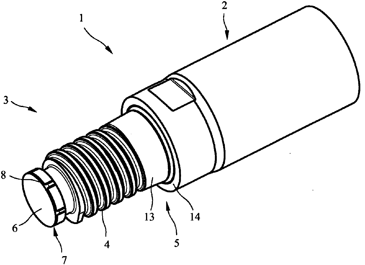
[0029] exist figure 1 shows a screw-in tool 1 with a tool head 2 and a tool shank 3 . A cutting edge (not shown) is arranged on the tool head 2 for cutting a workpiece. The tool shank 3 has an external thread 4 , a first support region 5 arranged between the tool head 2 and the external thread 4 and a second support region arranged between the free end 6 of the tool shank 3 and the external thread 4 7. The free end 6 is formed by the end face of the tool shank 3 .

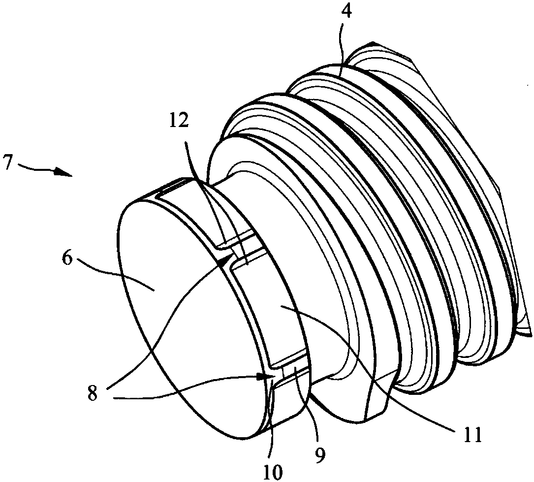
[0030] The first support region 7 has support elements 8 spaced apart from one another in the circumferential direction and projecting radially outward. refer to figure 2 The configuration of the support member 8 is described in detail.

[0031] exist figure 2 shown in detail in figure 1 The second support area 7 of the screw-in tool 1. As can be seen in the figure, the support elements 8 are designed as webs extending in the axial direction of the screw-in tool 1 and spaced evenly from one another. In t...


PUM


Abstract

The invention relates to a screwing tool (1) comprising a tool head (2) and a tool shaft (3); the tool shaft (3) has an external thread (4), a first support section (5) between the tool head (2) and the external thread (4), and a second support section (7) between the external thread (4) and a free end (6) of the tool shaft (3). According to the invention, the second support section (7) includes supporting elements (8) which project radially outward and are located at a distance from one another in the circumferential direction.

Description

technical field [0001] The invention relates to a screw-in tool according to the preamble of claim 1 , a tool holder / tool ​​holder and a tool arrangement. Background technique [0002] A screw-in tool with tool holder is known from document DE 10 2012 100 976 A1. The screw-in tool includes a tool head and a tool shank. A cutting edge is arranged on the tool head for cutting. The tool shank has an external thread for connecting with a tool holder. On the tool shank, a first support region is also formed between the tool head and the external thread, and a second support region is also formed adjacent to the free end of the tool shank. For this purpose, the tool holder each comprises a receiving bore with an internal thread and a first bearing region arranged between the front side of the tool holder and the inner thread and a second bearing region arranged at the inner end of the receiving bore. The first support area of ​​the screw-in tool is in contact with the first supp...

Claims


Application Information

Patent Timeline
Patent Type & Authority Applications(China)
IPC IPC(8): B23C5/10
CPCB23B31/005B23B31/1122B23B2231/0204B23C5/10B23C2210/02B23C2240/32B23B2250/16B23B2265/08B23B2270/12
Inventor F·海莫
Owner FRANZ HAIMER MASCHINENBAU KG
Why Eureka
Try Eureka