
Compressor assembly and refrigerator with compressor assembly

A technology for compressors and components, applied in machines/engines, pump components, household appliances, etc., can solve the problems of loud compressor noise, affect user experience, and difficulty in compressor installation, and achieve the effect of easy installation.

Inactive Publication Date: 2018-04-17
QINGDAO HAIER SMART TECH R & D CO LTD +1
View PDF4 Cites 1 Cited by
  • Summary
  • Abstract
  • Description
  • Claims
  • Application Information

AI Technical Summary

Problems solved by technology

[0002] The compressor is the key equipment for refrigerator operation and refrigeration. At present, the existing design of the compressor still has the following technical problems: when the refrigerator is running, the vibration of the compressor will generate a lot of noise, which affects the user experience; when the compressor is installed, the bottom of the compressor will The multiple mounting feet of the refrigerator and the multiple corresponding mounting parts in the refrigerator often cannot be matched in place at the same time (for example, the compressor has four mounting feet, which need to be fixed on the mounting plate inside the refrigerator, which may There will be three mounting feet abutted to the corresponding installation position on the fixed plate, and the fourth installation foot cannot be abutted to its corresponding installation position), which will bring certain difficulties to the installation of the compressor

Method used


Image

  • Compressor assembly and refrigerator with compressor assembly
  • Compressor assembly and refrigerator with compressor assembly
  • Compressor assembly and refrigerator with compressor assembly

Examples


Embodiment Construction

[0024] The present invention will be described in detail below in conjunction with various embodiments shown in the accompanying drawings, please refer to Figure 1 to Figure 9 As shown, it is some preferred embodiments of the present invention.

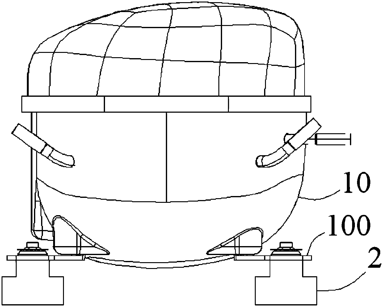
[0025] refer to figure 1 As shown, the refrigerator in the present invention includes a box body 1, a chamber is provided at the bottom of the box body 1, and a compressor assembly is housed in the chamber, specifically, the compressor assembly is supported and fixed in the chamber by a plurality of hydraulic feet 2 On the mounting plate 11 in the room. In other embodiments of the present invention, the location of the chamber can also be located at other locations inside the refrigerator.

[0026] refer to figure 2 As shown, the compressor assembly in the present invention includes a compressor body 10 , and the compressor assembly also includes several oil pressure feet 2 arranged at the bottom of the compressor body 10 to supp...


PUM


Abstract

The invention discloses a compressor assembly and a refrigerator with the compressor assembly. The compressor assembly comprises a compressor body and a plurality of oil pressure feet arranged on thebottom part of the compressor body and used for supporting the compressor body, wherein each oil pressure foot comprises a cylinder body fixedly arranged relative to the compressor body and provided with an oil storage cavity formed inside, a plunger arranged in the corresponding oil cavity and capable of moving up and down relative to the corresponding cylinder body, and a fixing foot connected under the corresponding plunger; and the oil cavity of each oil pressure foot communicates with the oil cavity of the other oil pressure foot so as to enable the corresponding fixing feet to align in an up-and-down direction. According to the compressor assembly and the refrigerator with the compressor assembly provided by the invention, through the communicating oil pressure feet, the vibration energy produced during a compressor operation process can be effectively absorbed, so that the generation of a larger noise is avoided; and during an installation process of the compressor assembly, thecommunicating oil pressure feet can be adaptively adjusted, so that the fixing feet of the oil pressure feet can be simultaneously abutted against corresponding installation part positions in the refrigerator, and the compressor assembly is conveniently installed in the refrigerator.

Description

technical field [0001] The invention relates to the field of household appliances, in particular to a compressor assembly and a refrigerator with the compressor assembly. Background technique [0002] The compressor is the key equipment for refrigerator operation and refrigeration. At present, the existing design of the compressor still has the following technical problems: when the refrigerator is running, the vibration of the compressor will generate a lot of noise, which affects the user experience; when the compressor is installed, the bottom of the compressor will The multiple mounting feet of the refrigerator and the multiple corresponding mounting parts in the refrigerator often cannot be matched in place at the same time (for example, the compressor has four mounting feet, which need to be fixed on the mounting plate inside the refrigerator, which may It will happen that after the three mounting feet abut against the corresponding installation part position on the fi...

Claims


Application Information

Patent Timeline
Patent Type & Authority Applications(China)
IPC IPC(8): F04B39/00F25D23/00
CPCF04B39/0044F25D23/006
Inventor 宋斌许升高山吴远刚李孟成
Owner QINGDAO HAIER SMART TECH R & D CO LTD
Learn More