Rotary, swing, drawing and pulling fitness device and achieving method
A technology of a fitness device and an implementation method, which is applied in the field of fitness equipment and can solve the problems of lack of fitness equipment and the like
- Summary
- Abstract
- Description
- Claims
- Application Information
AI Technical Summary
Problems solved by technology
Method used
Image
Examples
Embodiment 1
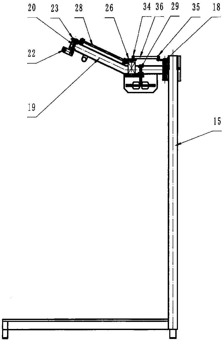
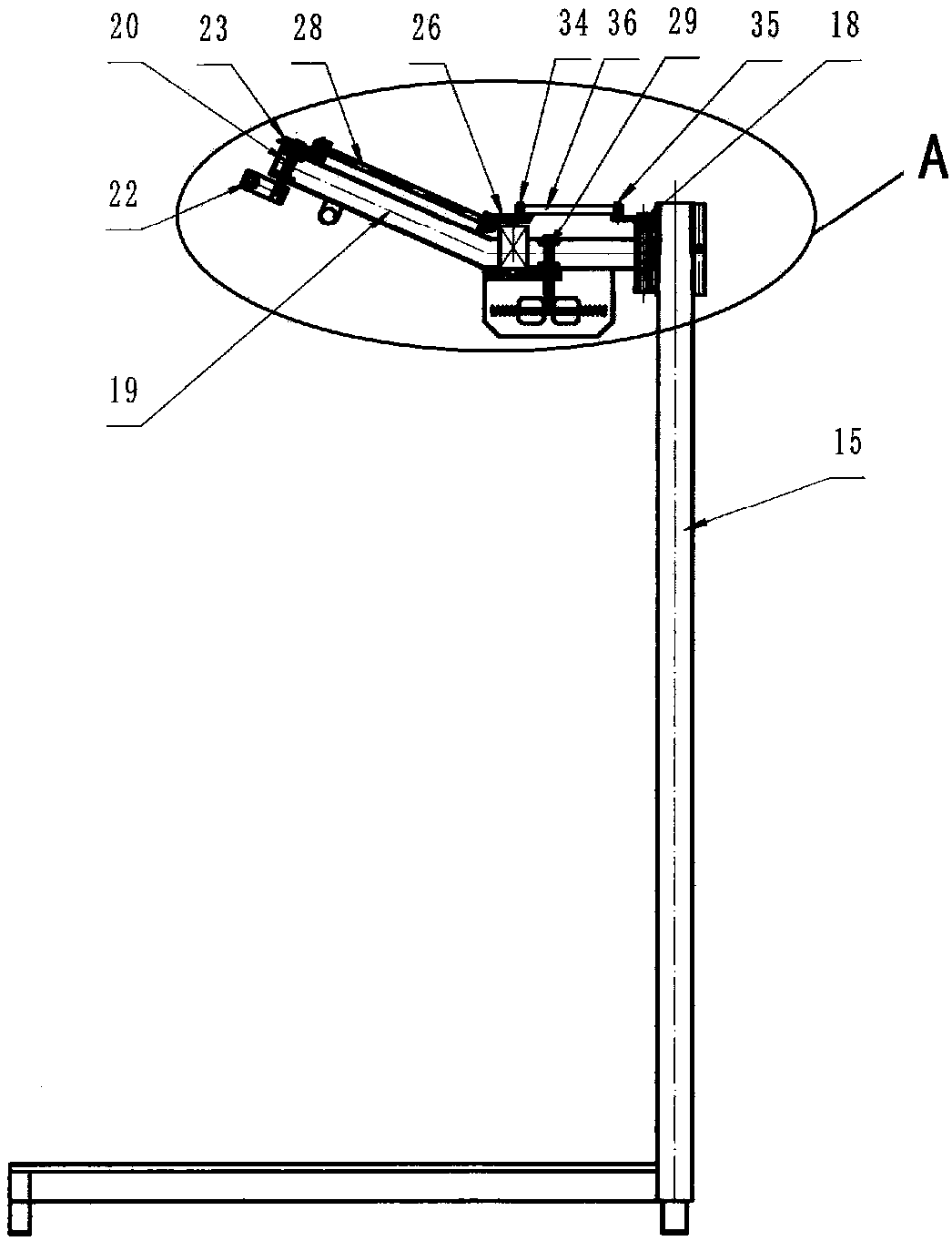
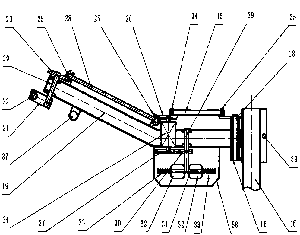
[0029] Embodiment 1: Inertia power-assisted rotary pendulum pulls fitness equipment, as Figure 4As shown, one end of a swing arm pipe 19 is hingedly mounted on the support 16 through the shaft 18, and a rotating rod 22 is used as a handle to fix its middle part on the rotating shaft 20 at the other end of the swing arm pipe 19, the axis of the rotating shaft 20 O1 forms a certain angle with the axis O2 of the shaft 18 to ensure that the height of the end of the swing arm tube away from the swing arm tube increases when the rotary rod 22 rotates, and the height of the end close to the swing arm tube decreases. A gear 43 and a disk 41 are also fixed on the rotating shaft 20, and a limit block 42 and a short shaft 34 are fixed on the disk 41, and their positions are as shown in the figure. A pair of limit rebound devices 37 are arranged on the swing arm tube 19 , and when the limit block 42 rotates to the limit position with the rotary rod 22 , the impact 37 plays a role of limi...
Embodiment 2
[0031] Embodiment 2: motor-assisted rotary pendulum stretching fitness device, such as Figure 4 As shown, one end of a swing arm pipe 19 is hingedly mounted on the support 16 through the shaft 18, and a rotating rod 22 is used as a handle to fix its middle part on the rotating shaft 20 at the other end of the swing arm pipe 19, the axis of the rotating shaft 20 O1 forms a certain angle with the axis O2 of the shaft 18 to ensure that the height of the end of the swing arm tube away from the swing arm tube increases when the rotary rod 22 rotates, and the height of the end close to the swing arm tube decreases. A gear 43 and a disk 41 are also fixed on the rotating shaft 20, and a limit block 42 and a short shaft 34 are fixed on the disk 41, and their positions are as shown in the figure. A pair of limit rebound devices 37 are arranged on the swing arm tube 19 , and when the limit block 42 rotates to the limit position with the rotary rod 22 , the impact 37 plays a role of limi...
Embodiment 3
[0033] Embodiment 3: Elastic power-assisted rotary pendulum pulls fitness equipment, such as Figure 6 As shown, one end of a swing arm pipe 19 is hingedly mounted on the support 16 through the shaft 18, and a rotating rod 22 is used as a handle to fix its middle part on the rotating shaft 20 at the other end of the swing arm pipe 19, the axis of the rotating shaft 20 O1 forms a certain angle with the axis O2 of the shaft 18 to ensure that the height of the end of the swing arm tube away from the swing arm tube increases when the rotary rod 22 rotates, and the height of the end close to the swing arm tube decreases. A disc 50 and a disc 41 are also fixed on the rotating shaft 20 , and a limit block 42 and a short shaft 34 are fixed on the disc 41 , and their positions are as shown in the figure. A pair of limit rebound devices 37 are arranged on the swing arm tube 19 , and when the limit block 42 rotates to the limit position with the rotary rod 22 , the impact 37 plays a role...
PUM
 Abstract
Description
Claims
Application Information
 - R&D
- Intellectual Property
- Life Sciences
- Materials
- Tech Scout
- Unparalleled Data Quality
- Higher Quality Content
- 60% Fewer Hallucinations
Browse by: Latest US Patents, China's latest patents, Technical Efficacy Thesaurus, Application Domain, Technology Topic, Popular Technical Reports.
© 2025 PatSnap. All rights reserved.Legal|Privacy policy|Modern Slavery Act Transparency Statement|Sitemap|About US| Contact US: help@patsnap.com


