
Large dynamic range optical carrier radio frequency link system

A technology with large dynamic range and optical radio frequency, which is applied in the transmission system, electromagnetic wave transmission system, optical fiber transmission, etc., can solve the problems of deteriorating signal quality, limited application, and low dynamic range of the link, and achieve improved dynamic range and strong The effect of operability and simple structure

Inactive Publication Date: 2018-04-13
NORTHWESTERN POLYTECHNICAL UNIV
View PDF6 Cites 12 Cited by
  • Summary
  • Abstract
  • Description
  • Claims
  • Application Information

AI Technical Summary

Problems solved by technology

[0003] To transmit radio frequency signals through optical fibers, they must first be modulated by an optical carrier at the sending end. After the optical fiber is transmitted to the receiving end, photoelectric detection restores the radio frequency signal. Generates second- and third-order intermodulation distortion, resulting in lower link dynamic range and degrading signal quality
[0004] At present, many optimized design schemes of optical radio frequency links aiming at suppressing the second-order or third-order intermodulation distortion have been publicly reported, but most of them are difficult to suppress the second-order and third-order intermodulation distortion at the same time, and the overall dynamic range of the link is low, resulting in application limited

Method used


Image

  • Large dynamic range optical carrier radio frequency link system
  • Large dynamic range optical carrier radio frequency link system
  • Large dynamic range optical carrier radio frequency link system

Examples


Embodiment Construction

[0016] The present invention will be further described below in conjunction with the accompanying drawings and embodiments.

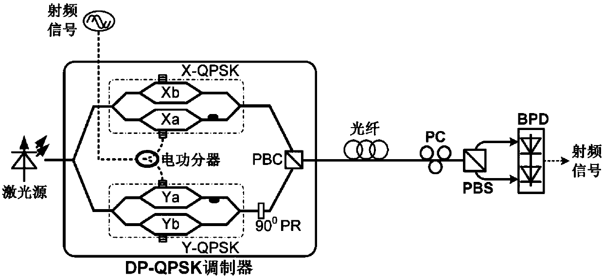
[0017] Such as figure 1 As shown, the optical radio frequency link system includes a laser source, a DP-QPSK modulator, an electrical power splitter, an optical fiber, a polarization controller (Polarization Controller, PC), a polarization beam splitter (Polarization Beam Splitter, PBS) and Balanced photodetector (Balanced Photodetector, BPD), the optical signal of the laser source is input to the optical signal input end of the DP-QPSK modulator, and the optical signal is connected to one end of the PC after connecting the optical fiber from the output end of the DP-QPSK modulator, The other end of the PC is connected to the common input terminal of the PBS, and the two output terminals of the PBS are respectively connected to the two optical signal input terminals of the BPD; the RF signal is connected to the electric power divider, and the two output...


PUM


Abstract

The invention provides a large dynamic range optical carrier radio frequency link system, and relates to the technical field of optical fiber communication. According to the invention, the optical carrier radio frequency link adopts a dual polarization quadrature phase shift keying modulator to realize electro-optic modulation; a radio frequency signal drives the modulator in a push-pull mode; bias point optimization and balance detection of the modulator are combined to enable simultaneous suppression of second-order and third-order intermodulation distortion in the recovered radio frequencysignal, so as to substantially increase the dynamic range of the link; the DP-QPSK modulator is driven in the push-pull mode; third-order intermodulation distortion is suppressed by adjusting the operating point of each QPSK modulator; second-order intermodulation distortion is suppressed through balance detection; second-order intermodulation distortion and third-order intermodulation distortionare simultaneously suppressed; the suppression effect of second-order intermodulation distortion and third-order intermodulation distortion is improved by using an electrical power divider with a highdegree of balance, high-symmetry modulators, precise bias control and BPD with good responsivity balance and high common-mode rejection ratio; and the dynamic range is increased.

Description

technical field [0001] The invention relates to the technical field of optical fiber communication, in particular to an optical radio frequency link system. Background technique [0002] The radio frequency signal loses a lot in the atmosphere and cables, so it is not suitable for long-distance transmission. The optical fiber has the advantages of low loss, large bandwidth, no electromagnetic interference, and light weight. Therefore, an optical radio frequency link is constructed to transmit the radio frequency signal through the optical fiber. [0003] To transmit radio frequency signals through optical fibers, they must first be modulated by an optical carrier at the sending end. After the optical fiber is transmitted to the receiving end, photoelectric detection restores the radio frequency signal. Second-order and third-order intermodulation distortions are generated, resulting in lower link dynamic range and degrading signal quality. [0004] At present, many optimiz...

Claims


Application Information

Patent Timeline
Patent Type & Authority Applications(China)
IPC IPC(8): H04B10/2575H04B10/556H04B10/69
Inventor 高永胜樊养余谭庆贵
Owner NORTHWESTERN POLYTECHNICAL UNIV
Learn More