
Method for controlling wind turbine to participate in power grid frequency modulation based on virtual inertia and pitch angle

A wind turbine and virtual inertia technology, applied in wind power generation, electrical components, circuit devices, etc., can solve problems such as inability to respond to grid frequency changes, system inertia reduction, etc.

Inactive Publication Date: 2018-04-13
SOUTHWEST JIAOTONG UNIV
View PDF0 Cites 19 Cited by
  • Summary
  • Abstract
  • Description
  • Claims
  • Application Information

AI Technical Summary

Problems solved by technology

[0003] At present, the ability to respond to system frequency has become an important feature of "grid-friendly" wind power. As a mainstream model of grid-connected wind power, variable-speed constant-frequency doubly-fed wind turbines (DFIG) can flexibly adjust active and reactive power, but power electronics The converter hides the coupling relationship between the speed of the wind turbine and the frequency of the grid, which makes it unable to respond to changes in the grid frequency. When large-scale wind turbines are connected to the grid, it will inevitably lead to problems such as reduced system inertia.

Method used


Image

  • Method for controlling wind turbine to participate in power grid frequency modulation based on virtual inertia and pitch angle
  • Method for controlling wind turbine to participate in power grid frequency modulation based on virtual inertia and pitch angle
  • Method for controlling wind turbine to participate in power grid frequency modulation based on virtual inertia and pitch angle

Examples


Embodiment Construction

[0043] The specific embodiments of the present invention are described below so that those skilled in the art can understand the present invention, but it should be clear that the present invention is not limited to the scope of the specific embodiments. For those of ordinary skill in the art, as long as various changes Within the spirit and scope of the present invention defined and determined by the appended claims, these changes are obvious, and all inventions and creations using the concept of the present invention are included in the protection list.

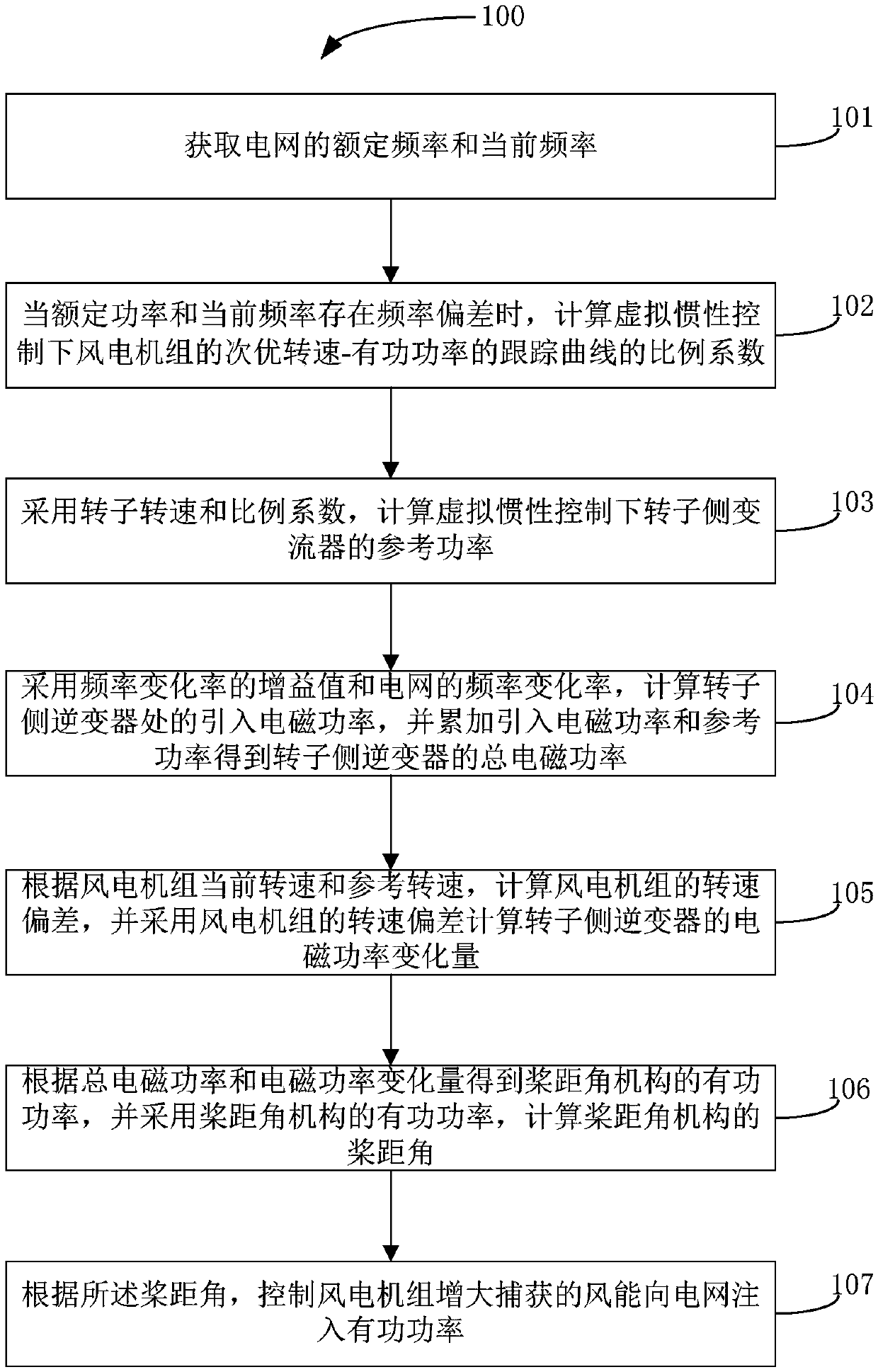
[0044] refer to figure 1 , figure 1 A flow chart showing an embodiment of a method for controlling wind turbines to participate in power grid frequency regulation based on virtual inertia and pitch angle; figure 1 As shown, the method includes step 101 to step 107.

[0045] In step 101, after obtaining the rated frequency and the current frequency of the power grid, the relationship between the rated frequency and the cur...


PUM


Abstract

The invention discloses a method for controlling a wind turbine to participate in power grid frequency modulation based on virtual inertia and a pitch angle. The method comprises the following steps:when a frequency deviation exists between the rated power of a system power grid and the current frequency, calculating a proportionality factor of a tracking curve of the sub-optimal rotating speed-active power of the wind turbine under the control of the virtual inertia; calculating a reference power of an inverter at a rotor side under the control of the virtual inertia; calculating an introduced electromagnetic power at the rotor side inverter according to the frequency change rate, and accumulating the introduced electromagnetic power and the reference power to obtain a total electromagnetic power of the rotor side inverter; calculating the rotating speed deviation of the wind turbine, and adopting the rotating speed deviation of the wind turbine to calculate the electromagnetic powervariation of the rotor side inverter; obtaining an active power of a pitch angle mechanism according to the total electromagnetic power and the electromagnetic power variation, and calculating the pitch angle of the pitch angle mechanism by adopting the active power of the pitch angle mechanism; and controlling the wind turbine to increase captured wind energy and inject the active power into thepower grid according to the pitch angle.

Description

technical field [0001] The invention belongs to the technical field of wind power generation, and in particular relates to a method for controlling wind turbines to participate in power grid frequency regulation based on virtual inertia and pitch angle. Background technique [0002] At present, wind power generation has been rapidly developed in countries all over the world. With the increasing proportion of wind power in the power grid, a series of challenges have been brought to the safe and stable operation of the power system. [0003] At present, the ability to respond to system frequency has become an important feature of "grid-friendly" wind power. As a mainstream model of grid-connected wind power, variable-speed constant-frequency doubly-fed wind turbines (DFIG) can flexibly adjust active and reactive power, but power electronics The converter hides the coupling relationship between the speed of the wind turbine and the grid frequency, which makes it unable to respo...

Claims


Application Information

Patent Timeline
IPC IPC(8): H02J3/38H02J3/24
CPCH02J3/386H02J3/24H02J2203/20Y02E10/76
Inventor 王德林刘柳张俊武张晨曦白雁翔康积涛
Owner SOUTHWEST JIAOTONG UNIV
Learn More