A device for supporting optical elements

A technology for optical components and placing tables, which is applied in the direction of optical components, optics, installation, etc., can solve problems affecting the surface shape of optical components, reduce assembly and fixing stress, avoid surface shape being affected, and eliminate radial forces.

Active Publication Date: 2019-10-25
CHANGCHUN INST OF OPTICS FINE MECHANICS & PHYSICS CHINESE ACAD OF SCI
View PDF3 Cites 0 Cited by
  • Summary
  • Abstract
  • Description
  • Claims
  • Application Information

AI Technical Summary

Problems solved by technology

[0002] Optical components are usually fixed by a support structure. During the process of assembling the optical component to the support structure, a force or moment acting on the optical component will be generated, which will cause a small deformation of the optical component and affect the surface shape of the optical component.

Method used


Image

  • A device for supporting optical elements
  • A device for supporting optical elements
  • A device for supporting optical elements

Examples


Embodiment 1

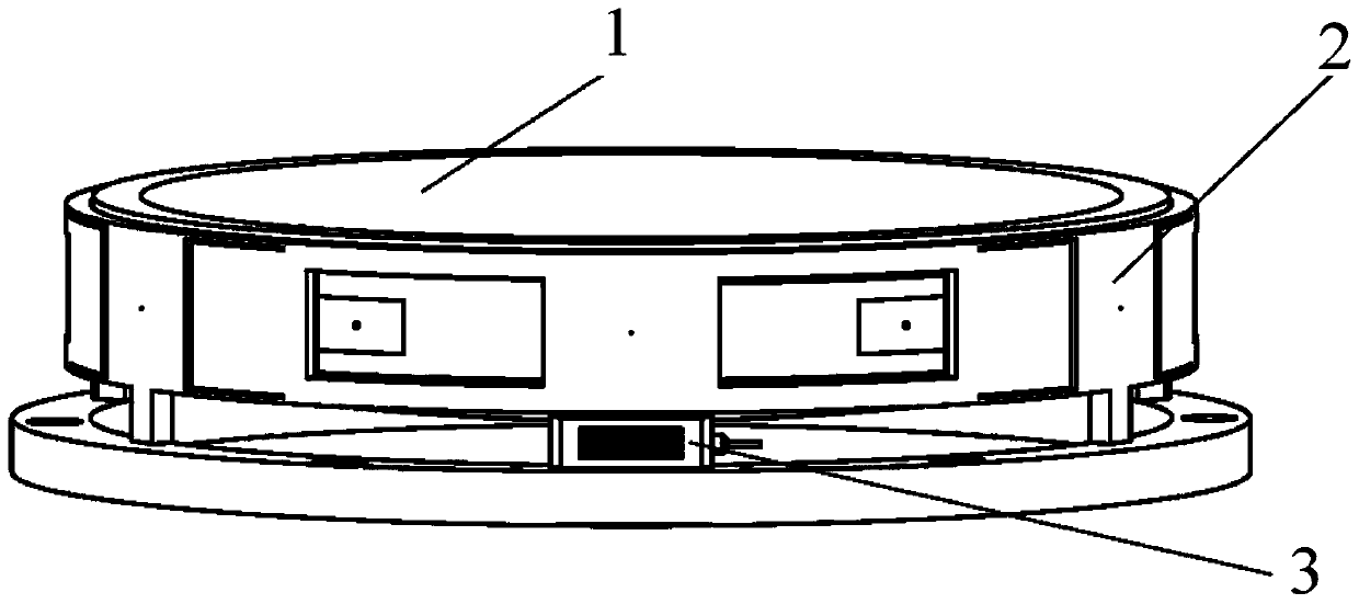
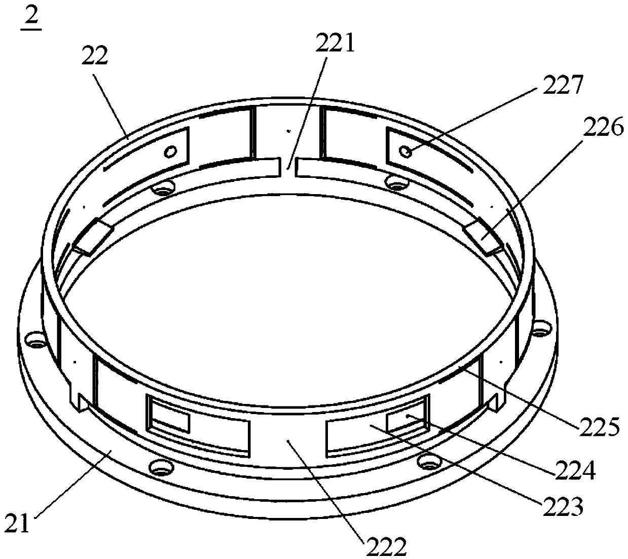
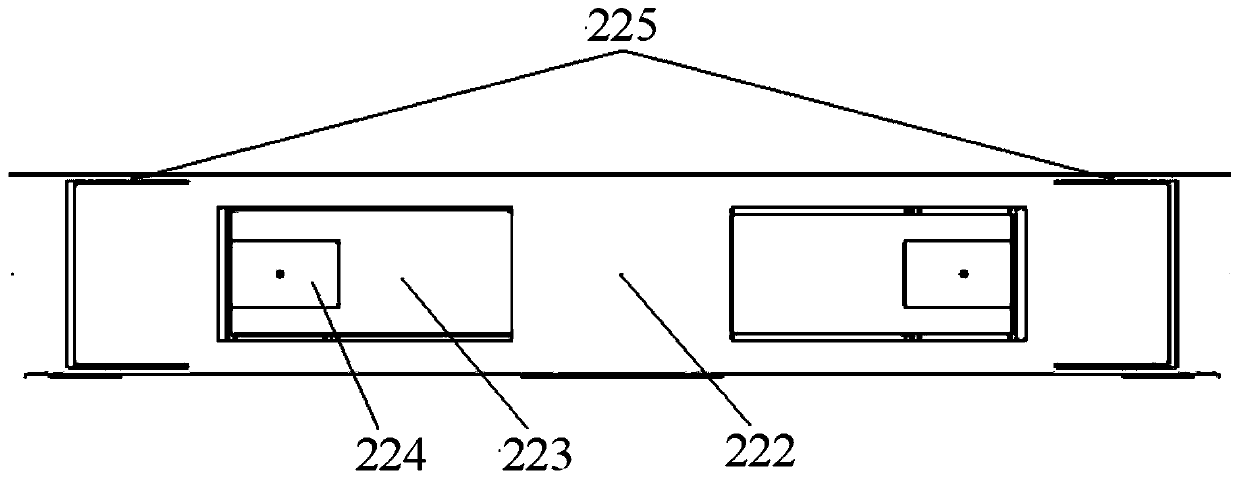
[0027] see Figure 1 ~ Figure 3 , figure 1 It is a diagram of the use state of a device for supporting optical elements provided by Embodiment 1 of the present invention; figure 2 yes figure 1 Schematic diagram of middleware 2; image 3 yes figure 1 Partial schematic diagram of middleware 2.

[0028] The device for supporting optical elements provided by Embodiment 1 includes a support frame 2, which includes a horizontally arranged base 21 and an annular body 22 above the base 21, such as figure 2 As shown, the axis of the ring body 22 is in the vertical direction, and the lower end surface of the ring body 22 has a plurality of legs 221 evenly distributed around the axis, the legs 221 are fixedly connected to the base 21, and the ring body 22 is located at the front of the legs 221. The part above is called the fixed segment (unmarked among the figures), and the part of the annular body 22 that is positioned between two adjacent fixed segments is called the floating s...

Embodiment 2

[0036] Such as figure 2 As shown, in the first embodiment, the upper surface of the placing platform 226 is an inclined surface, and one end of the inclined surface close to the center of the annular body 22 is lower than the other end. The difference between the second embodiment and the first embodiment is that the placing platform 226 has different shapes. In the second embodiment, the upper surface of the placing platform 226 is a horizontal plane.

[0037] In each of the above embodiments, the number of legs 221 may be 3-5. In order to be able to adjust the posture of the optical element 1, a plurality of linear actuators 3 equal in number to the legs 221 can also be provided, and the plurality of linear actuators 3 are evenly distributed around the axis of the annular body 22, and are located in the center of the floating section 222. Directly below. In addition, for the convenience of control, a controller can be provided, and a plurality of linear actuators 3 are el...


PUM


Abstract

The invention provides a device for supporting optical elements, comprising a horizontally arranged base (21) and an annular body (22) above the base (21), the lower end surface of the annular body (22) has a plurality of The supporting legs (221) whose axes are evenly distributed, the supporting legs (221) are fixedly connected with the base (21), and the part of the annular body (22) located directly above the supporting legs (221) is called a fixed section, and the annular body (22) The part between two adjacent fixed segments is called floating segment (222), the two ends of the floating segment (222) have arm bars (225) fixedly connected with the fixed segment, and the middle part of the floating segment (222) has The platform (226) is placed, and the floating section (222) is also provided with a U-shaped through hole for forming the tongue piece (223). Using the device provided by the invention to support the optical element can effectively reduce assembly and fixing stress, thereby preventing the surface shape of the optical element from being affected.

Description

technical field [0001] The invention relates to the technical field of optical element support structures, in particular to a device for supporting optical elements. Background technique [0002] Optical components are usually fixed by a support structure. During the process of assembling the optical component to the support structure, a force or moment will be generated on the optical component, which will cause a small deformation of the optical component and affect the surface shape of the optical component. For high-precision optical components, the influence of the above-mentioned small deformation on the surface shape can not be ignored. Therefore, how to improve the support structure to reduce the assembly and fixing stress, so as to avoid affecting the surface shape of the optical components as much as possible, Become a technical problem to be solved urgently by those skilled in the art. Contents of the invention [0003] In view of this, the present invention pr...

Claims


Application Information

Patent Timeline
Patent Type & Authority Patents(China)
IPC IPC(8): G02B7/00
CPCG02B7/00
Inventor 周烽王辉郭本银谢耀王丽萍
Owner CHANGCHUN INST OF OPTICS FINE MECHANICS & PHYSICS CHINESE ACAD OF SCI
Why Eureka
Try Eureka