
Stator frame welding deflection tool and application method thereof

A stator frame, welding displacement technology, applied in welding equipment, auxiliary welding equipment, welding/cutting auxiliary equipment, etc., can solve the problems of inability to stand welding by workers, inability to weld rib plates, and low welding efficiency. It is not easy to achieve. The effect of loosening, improving efficiency and saving cost

Active Publication Date: 2018-04-10
DEYANG JIUDING ELECTRIC CO LTD
View PDF6 Cites 1 Cited by
  • Summary
  • Abstract
  • Description
  • Claims
  • Application Information

AI Technical Summary

Problems solved by technology

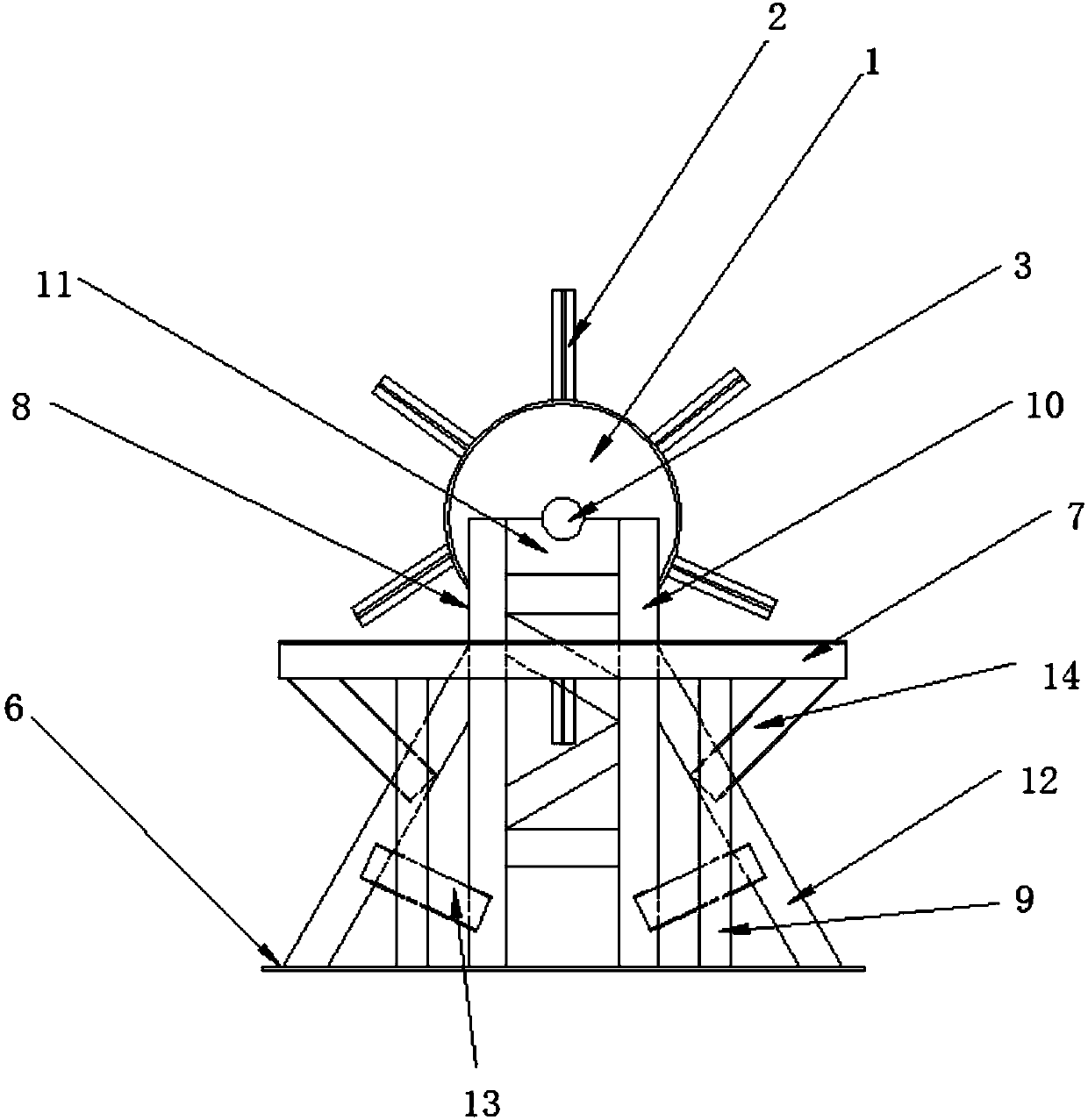
[0003] The purpose of the present invention is: in order to solve the problem that the frame is placed horizontally on the ground, for each rib plate, it is welded from top to bottom or from bottom to top, and the workers have to squat on the ground to weld the rib plate, and the There are many welding points on the frame, and the position of the welding workpiece needs to be constantly changed. However, the existing positioning tooling cannot allow the workers to achieve standing welding, and the stator frame is fixed so that the workers cannot weld the ribs at the same place, resulting in the final welding In order to solve the problems of low efficiency and worker fatigue, the present invention provides a stator frame welding displacement tool

Method used


Image

  • Stator frame welding deflection tool and application method thereof
  • Stator frame welding deflection tool and application method thereof
  • Stator frame welding deflection tool and application method thereof

Examples


Embodiment Construction

[0028] The technical solution in this embodiment will be clearly and completely described below in conjunction with the accompanying drawings in the embodiment of the present invention. Obviously, the described embodiment is only a part of the embodiments of the present invention, not all of the embodiments. Based on the embodiments of the present invention, all other embodiments obtained by persons of ordinary skill in the art without making creative efforts belong to the protection scope of the present invention.

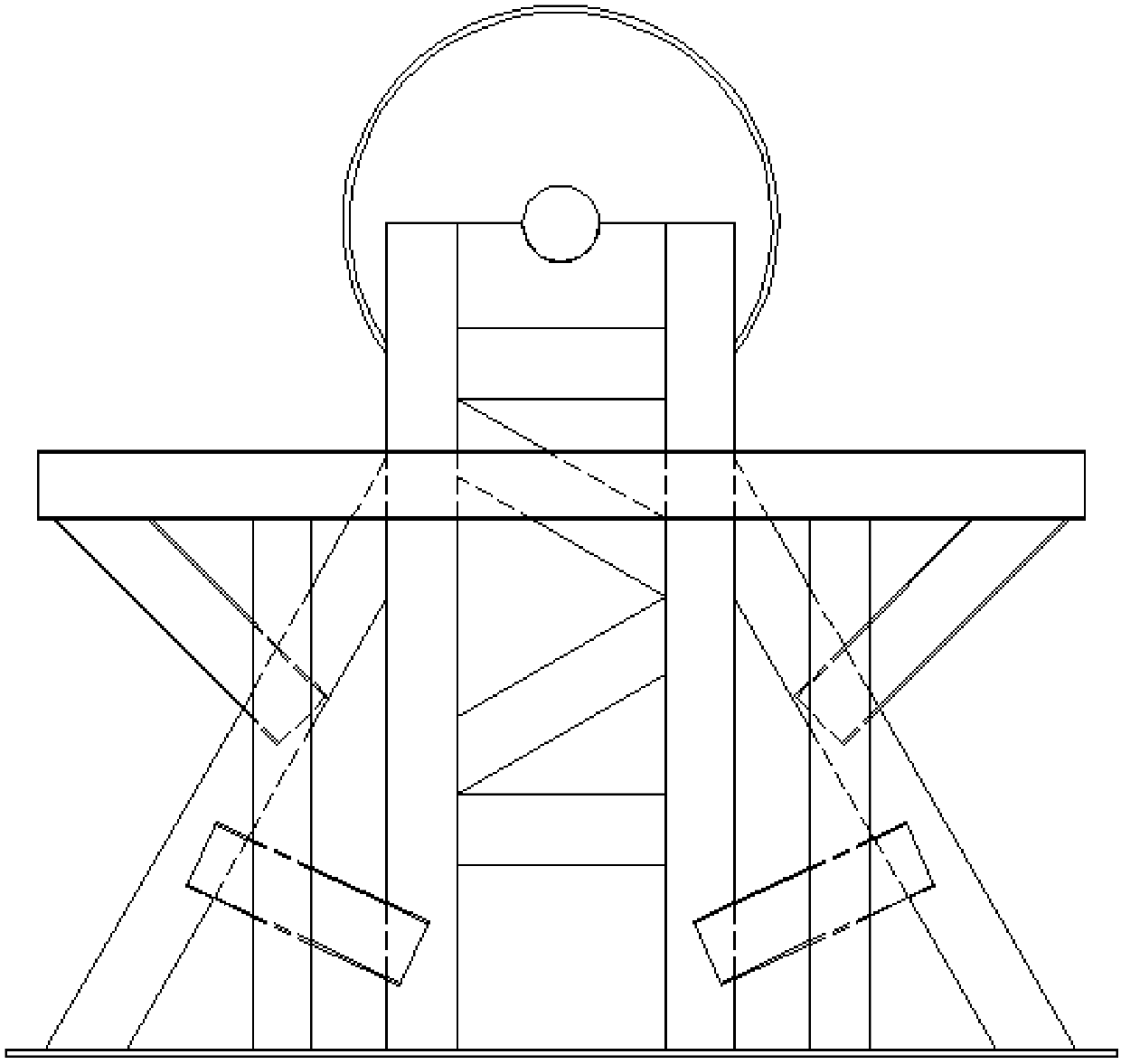
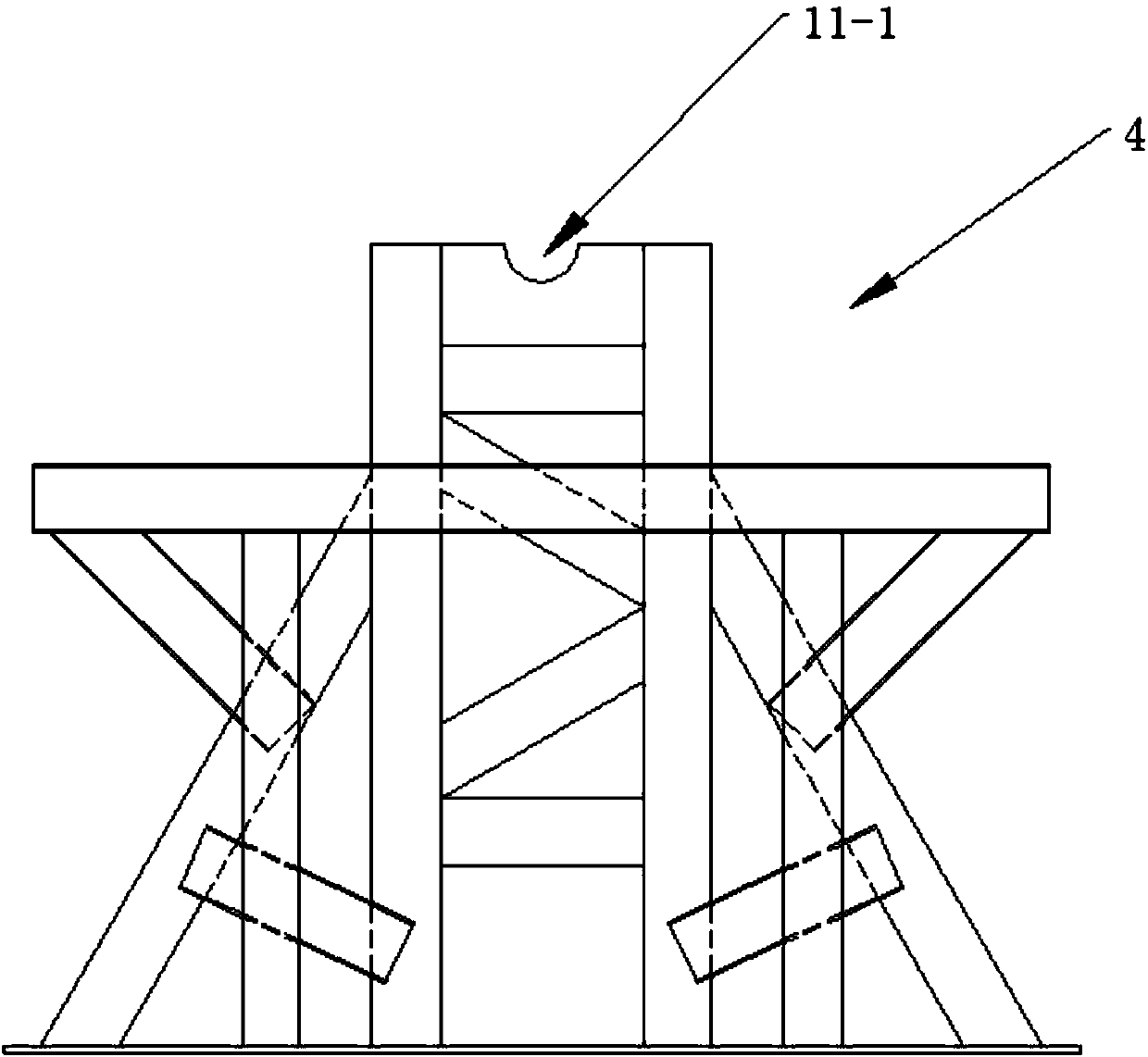
[0029] Such as figure 1 As shown, a stator frame 5 welding displacement tooling includes a connecting cylinder 1, a connecting steel bar 2, a rotating shaft 3 and a rotating shaft supporting device 4 arranged on the connecting cylinder 1, and the connection between the connecting cylinder 1 and the stator frame 5 They are connected by connecting steel bars 2, and the rotating shaft 3 can rotate on the rotating shaft supporting device 4.

[0030] Such as image 3...


PUM


Abstract

The invention discloses a stator frame welding deflection tool and an application method thereof, and relates to the technical field of stator frame preparation. The stator frame welding deflection tool comprises a connecting cylinder, a connecting steel strip, a rotating shaft arranged on the connecting cylinder, and a rotating shaft support device; the connecting cylinder and a stator frame areconnected through the connecting steel strip; and the rotating shaft can be rotated on the rotating shaft support device. The internal structure of the stator frame is not drawn out; a traditional stator frame is horizontally placed on the ground; for each rib plate, the rib plates are welded from top to bottom or from bottom to top; workers need to squat on the ground to weld the rib plates; dueto more welding points of the stator frame, the workpiece welding positions need to be continuously changed; and a traditional positioning tool cannot enable workers to realize the standing welding, the stator frame is fixed, so that the workers cannot weld the rib plates in the same place, and the problems of low final welding efficiency and tiredness of the workers are generated.

Description

technical field [0001] The invention relates to the technical field of stator frame preparation, in particular to a welding displacement tool for a stator frame and a use method thereof. Background technique [0002] There are multiple ribs on the periphery of the stator frame, and these ribs are fixed on the stator frame by welding. The traditional welding positioning tool is mostly used to lock the workpiece, place the stator frame horizontally, and fix the welding points before proceeding. Welding, and the welding method is manual welding. Since the frame is placed horizontally on the ground, for each rib plate, it is welded from top to bottom or from bottom to top. Workers have to squat on the ground to weld the rib plate, and because There are many welding points on the stator frame, and the position of the welding workpiece needs to be constantly changed. However, the existing positioning tooling cannot allow workers to achieve standing welding, and the stator frame is...

Claims


Application Information

Patent Timeline
Patent Type & Authority Applications(China)
IPC IPC(8): B23K37/047
CPCB23K37/047
Inventor 温仕伟
Owner DEYANG JIUDING ELECTRIC CO LTD
Learn More