


Quick Research
Generate reliable direction feasibility study reports for your R&D in just a few steps.

Technical Q&A
Discover and master advanced knowledge NOW. Basics, ideas, possibilities, all at once.

Find Solutions
As an expert in R&D theories, this can generate solutions to your technical problems instantly.

Evaluate Feasibility
Analyze your overall solution with one click, know your potential R&D risks in advance.

Monitor Landscape
Get weekly tech updates, stay abreast of the latest tech innovations and key insights.
Image projection display method and optical engine
A technology of projection display and display method, applied in the field of projection display, can solve problems such as poor contrast of projection display images
- Summary
- Abstract
- Description
- Claims
- Application Information
AI Technical Summary
Problems solved by technology
Method used
Image


Examples
Embodiment 1
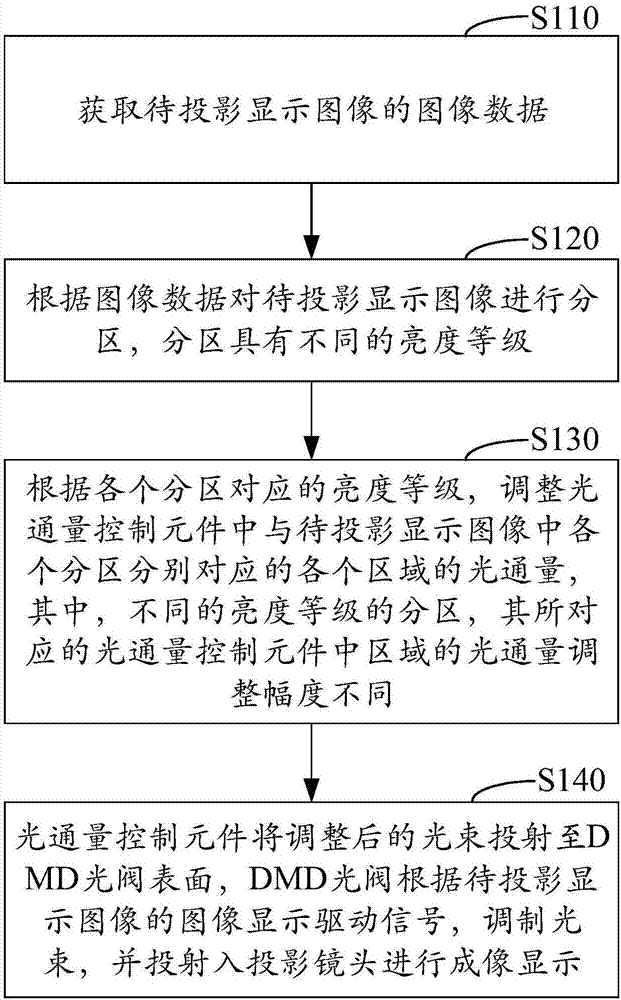
[0039] image 3 It is a flowchart of an image projection display method according to an exemplary embodiment. Such as image 3 As shown, the image projection display method may include the following steps.
[0040] In step S110, image data of an image to be projected and displayed is acquired.
[0041] During the use of the optical engine, the computer and other video signal output terminals convert the display data into video signals, and send them to the optical engine through the connection between the optical engine and the video signal output terminal. After the optical engine receives the video signal output by the video signal output terminal, it The video signal is processed to generate image data for an image to be projected and displayed.
[0042] Figure 4 It is a schematic diagram of signal processing performed by a DLP optical engine according to an exemplary embodiment. The light emitted by the light source 101 is processed by the optical system 102 and projec...
Embodiment 2
[0057] Figure 5 is a description of the details of step S120 shown according to an exemplary embodiment. In step S120, the step S120 may include the following steps.
[0058] In step S121, the brightness information and pixel position information of each pixel in the image data are extracted.
[0059] A pixel is the basic unit of an image, and an image is made up of pixels. The image data includes information such as brightness information and position information of each pixel and image display driving signals, and the brightness information and pixel position information of each pixel are extracted from the image data.
[0060] In step S122, according to the brightness information and pixel position information of each pixel, the partition corresponding to the brightness level in the image to be projected and displayed is determined.
[0061] There are many ways to determine the partition corresponding to the brightness level in the image to be projected and displayed ac...
Embodiment 3
[0068] Figure 7 is a description of the details of step S122 according to an exemplary embodiment. In step S122, the step S122 may include the following steps.
[0069] In step S1221, the brightness level existing in the image to be projected and displayed is determined according to the brightness information of each pixel.
[0070] According to the brightness information of each pixel, the brightness value is divided into a plurality of brightness ranges, and each brightness range corresponds to a brightness level.
[0071] There are many ways to determine the brightness level existing in the image to be projected and displayed. It may be that multiple brightness levels are preset in the optical engine according to the brightness value, and then according to the brightness information of each pixel in the image to be projected and displayed, determine the brightness level of the image to be projected and displayed. The brightness level existing in the image; it can also di...
PUM
 Abstract
Description
Claims
Application Information
 - R&D Engineer
- R&D Manager
- IP Professional
- Industry Leading Data Capabilities
- Powerful AI technology
- Patent DNA Extraction
Browse by: Latest US Patents, China's latest patents, Technical Efficacy Thesaurus, Application Domain, Technology Topic, Popular Technical Reports.
© 2024 PatSnap. All rights reserved.Legal|Privacy policy|Modern Slavery Act Transparency Statement|Sitemap|About US| Contact US: help@patsnap.com