Testing method of rock true triaxis with ultrasonic phased array real-time imaging system with

A real-time imaging system, ultrasonic phased array technology, applied in the direction of applying stable tension/pressure to test the strength of materials, measuring devices, instruments, etc., can solve the problem that the nature and size of the acoustic emission source cannot be given, the shape of the crack cannot be obtained, and Size, can only give the general location of cracks, etc., to achieve the effect of intuitive results, small size, and high resolution

Inactive Publication Date: 2018-04-06
INST OF ROCK AND SOIL MECHANICS - CHINESE ACAD OF SCI
View PDF13 Cites 9 Cited by
  • Summary
  • Abstract
  • Description
  • Claims
  • Application Information

AI Technical Summary

Problems solved by technology

However, on the one hand, acoustic emission technology needs to install several probes on the sample, which is not conducive to the application of load.
On the one hand, the position of the rock crack needs to be calculated from the spatial position of the probe and the time difference of the sound wave arriving at the probe. The result is not intuitive enough, and the error is large; on the other hand, the acoustic emission technology can only give the position, activity, and intensity of the acoustic emission source. , the nature and size of the defect in the acoustic emission source cannot be given, that is, only the approximate location of the crack can be given, and the shape and size of the crack cannot be obtained

Method used


Image

  • Testing method of rock true triaxis with ultrasonic phased array real-time imaging system with
  • Testing method of rock true triaxis with ultrasonic phased array real-time imaging system with
  • Testing method of rock true triaxis with ultrasonic phased array real-time imaging system with

Examples


Embodiment Construction

[0024] The implementation of the present invention will be described in detail below in conjunction with the accompanying drawings, but they do not constitute a limitation to the present invention, and are only examples. At the same time, the advantages of the present invention are clearer and easier to understand through the description.

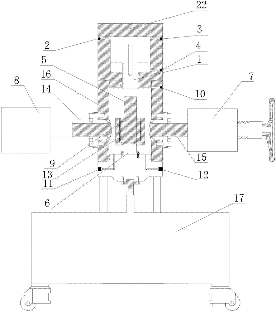
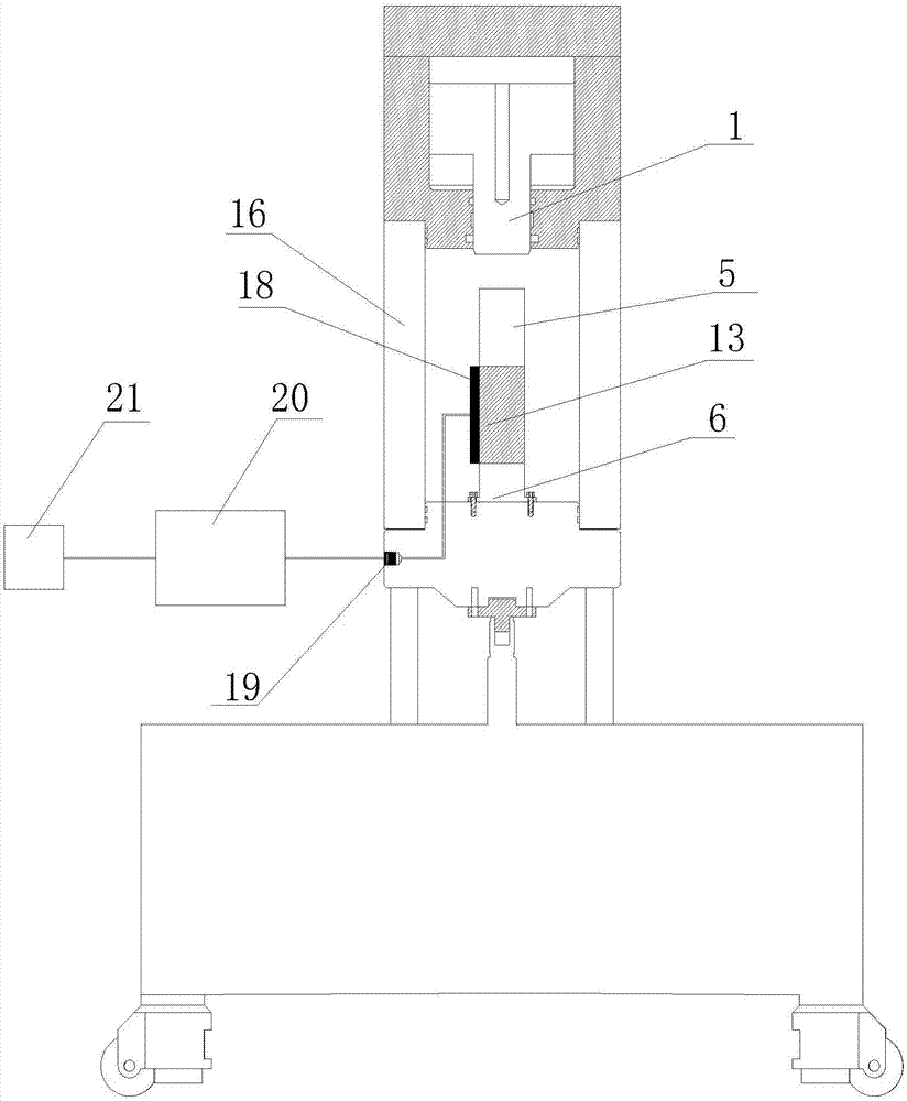
[0025] Referring to the accompanying drawings, it can be seen that the rock true triaxial test method with an ultrasonic phased array real-time imaging system is characterized in that it includes the following steps:

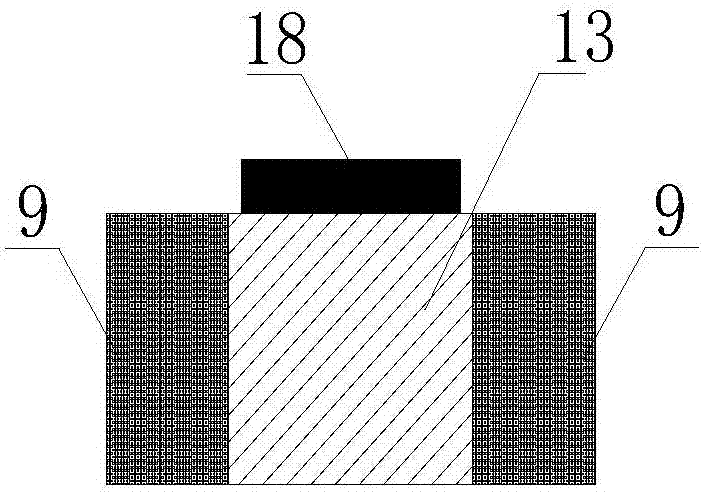
[0026] Step 1: Place the sample 13 between the square upper indenter 5 in the confining pressure chamber 16 and the square lower indenter 6 in the confining pressure chamber 16, and use rubber sleeves to place the sample 13 and the square upper indenter 5 And the square lower pressure head 6 sets, and the rubber sleeve is sealed with a clamp; a base 17 is arranged below the confining pressure chamber 16; the acoustic wave emi...


PUM

PropertyMeasurementUnit
sizeaaaaaaaaaa

Abstract

The invention discloses a testing method of rock true triaxis with an ultrasonic phased array real-time imaging system with, relating to a testing method of a rock true triaxis. The testing method comprises the following steps: putting a test sample between a square upper pressure head and a square lower pressure head, and coupling an ultrasonic phased array energy converter to the front or the back of the test sample through a coupling agent; operating a manual operating and loading part so as to ensure that the test sample does not deviate after operation; operating a pumping loading part soas to apply X-direction force to the test sample; transferring an electric pulse signal to the ultrasonic phased array energy converter through an upper computer during loading process; converting the electric pulse signal into a sound wave signal and transferring to the test sample through the ultrasonic phased array energy converter; and receiving the sound wave signal and generating an echo signal through the test sample, and transferring the echo signal to the ultrasonic phased array energy converter, converting the received echo signal into an electric signal through the ultrasonic phased array energy converter, and receiving the transferred electric signal and converting into images through the upper computer. The testing method has the advantages of being good in signal to noise ratio, high in resolution and convenient to use.

Description

technical field [0001] The invention relates to a rock true triaxial test method, in particular to a rock true triaxial test method with an ultrasonic phased array real-time imaging system. Background technique [0002] The mesoscopic mechanism is hidden behind the macroscopic phenomenon of rock deformation and cracking, that is, the evolution process of crack initiation, expansion, penetration and destruction on the mesoscopic scale. It is of great theoretical significance and application to find out the evolution law of cracks from the mesoscopic level. value. At present, most of the triaxial compression tests are carried out with industrial CT machines and self-developed loading devices to observe the internal crack propagation and evolution process during the rock failure process, and to a certain extent realize the real-time observation and analysis of the mesostructure during the rock failure process. [0003] The application number is: 201510577392.2, and the patent ...

Claims


Application Information

Patent Timeline
Patent Type & Authority Applications(China)
IPC IPC(8): G01N3/12
CPCG01N3/12G01N2203/0019G01N2203/0048
Inventor 胡大伟王冲周辉卢景景张传庆杨凡杰朱勇
Owner INST OF ROCK AND SOIL MECHANICS - CHINESE ACAD OF SCI
Why Eureka
Try Eureka