
Wall hanging furnace three-way valve control device and assembling and connecting method thereof

A technology for control devices and three-way valves, applied in valve devices, valve operation/release devices, valve details, etc., can solve problems such as increased assembly and connection steps, requirements for terminal installation accuracy, and increased difficulty in assembly and connection, to achieve assembly The connection method is convenient, the production efficiency is high, and the effect of simplifying the installation operation

Pending Publication Date: 2018-04-06
GUANGDONG WANHE THERMAL ENERGY TECH CO LTD
View PDF5 Cites 2 Cited by
  • Summary
  • Abstract
  • Description
  • Claims
  • Application Information

AI Technical Summary

Problems solved by technology

[0004] The existing three-way valve control device for wall-hung boilers is simple to control and easy to switch waterways. When controlling the device, the 250 terminals need to be installed on the mounting board one by one. Due to the large number of 250 terminals, the assembly and connection steps are increased, and because the terminal installation accuracy is also required, the excessive number of terminals makes the three-way valve control device of the wall-hung boiler more difficult. The difficulty of assembly and connection also increases

Method used


Image

  • Wall hanging furnace three-way valve control device and assembling and connecting method thereof
  • Wall hanging furnace three-way valve control device and assembling and connecting method thereof
  • Wall hanging furnace three-way valve control device and assembling and connecting method thereof

Examples


Embodiment Construction

[0046] In order to facilitate the understanding of the present invention, the present invention will be described more fully below with reference to the associated drawings. Preferred embodiments of the invention are shown in the accompanying drawings. However, the present invention can be embodied in many different forms and is not limited to the embodiments described herein. On the contrary, these embodiments are provided to make the understanding of the disclosure of the present invention more thorough and comprehensive.

[0047] It should be noted that when an element is referred to as being “fixed” to another element, it can be directly on the other element or there can also be an intervening element. When an element is referred to as being "connected to" another element, it can be directly connected to the other element or intervening elements may also be present.

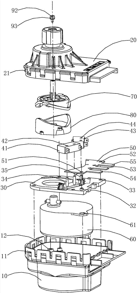
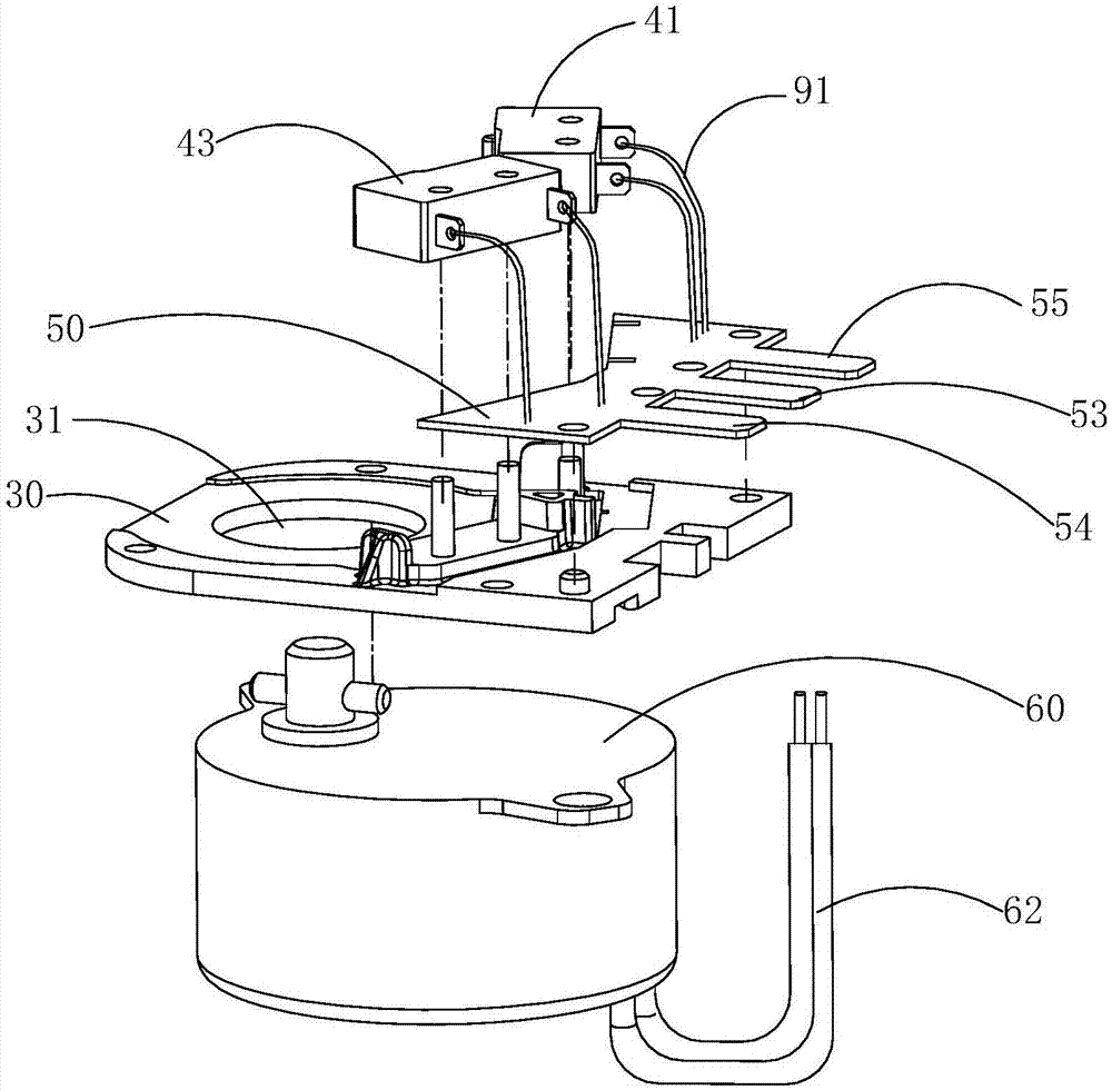
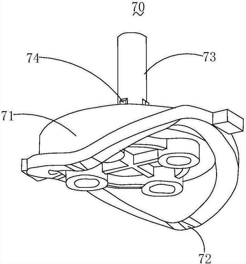
[0048] see Figure 1 to Figure 4, is a wall-hung boiler three-way valve control device in a preferred e...


PUM


Abstract

The invention discloses a wall hanging furnace three-way valve control device and an assembling and connecting method thereof. The wall hanging furnace three-way valve control device comprises an upper cover and a lower cover, a mounting space defined by the upper cover and the lower cover is internally provided with a mounting plate arranged on the lower cover , a bathroom microswitch, a heatingmicroswitch, a PCB, a motor arranged between the lower cover and the mounting plate, an ejection piece movably arranged on the side, close to the upper cover, of the mounting plate and a driving cam,wherein the bathroom microswitch, the heating microswitch and the PCB are arranged on the mounting plate; the bathroom microswitch and the heating microswitch are located between the mounting plate and the upper cover and located on one side of the PCB; the PCB is connected with the bathroom microswitch and the heating microswitch through an electric wire, and a lead of the motor is connected withthe PCB; and the ejection piece penetrates through the upper cover, the driving cam is located on one side of the bathroom microswitch and the heating microswitch, and the driving cam is connected with an output shaft, which penetrates through the mounting plate, of the motor and is abutted against the ejection piece. According to the device and the method, three 250 terminals are replaced by thePCB, so that the installation difficulty is reduced, and the assembly efficiency is improved.

Description

technical field [0001] The invention relates to a control device, in particular to a three-way valve control device for a wall-hung boiler and an assembly and connection method thereof. Background technique [0002] Three-way valves are widely used in wall-hung boilers, because in actual use, wall-hung boilers will alternately switch between the heating state and the sanitary state, and this conversion needs to be realized through a three-way valve. [0003] The three-way valve is easy to operate. When switching between waterways, you only need to change the power supply at both ends of the three-way valve; the three-way valve is generally one water inlet, one heating water outlet, and one bathroom water outlet. The power supply of the through valve can control the heating water or the bathroom water. At the same time, the three-way valve will only have one way of water out, and the other way out of water. The conversion of the three-way valve is realized by the three-way v...

Claims


Application Information

Patent Timeline
Patent Type & Authority Applications(China)
IPC IPC(8): F16K31/04F16K31/524
CPCF16K31/047F16K31/524
Inventor 卢楚鹏伍艺俊欧金桥
Owner GUANGDONG WANHE THERMAL ENERGY TECH CO LTD
Learn More