
Sand-plastic floor convenient to mount

A floor and sand plastic technology, applied in the field of sand plastic floor, can solve the problems of weak connection, floor lifting or displacement, affecting the service life of the floor, etc., achieving the effect of simple installation, prolonging service life and reducing use.

Inactive Publication Date: 2018-04-06
BEIJING RECHSAND SCI & TECH GRP
View PDF6 Cites 3 Cited by
  • Summary
  • Abstract
  • Description
  • Claims
  • Application Information

AI Technical Summary

Problems solved by technology

[0003] Therefore, the technical problem to be solved by the present invention is to overcome the weak connection between two adjacent floorboards in the horizontal and vertical directions in the prior art, which will easily cause the floor to warp or shift after long-term use and deformation, which will affect the use of the entire floor In order to provide a sand-plastic floor that is firmly connected in the horizontal and vertical directions between two adjacent floors, even if a small amount of deformation occurs after long-term use, it can ensure a firm connection and is easy to install.

Method used


Image

  • Sand-plastic floor convenient to mount
  • Sand-plastic floor convenient to mount
  • Sand-plastic floor convenient to mount

Examples


Embodiment Construction

[0029] The technical solutions of the present invention will be clearly and completely described below in conjunction with the accompanying drawings. Apparently, the described embodiments are some of the embodiments of the present invention, but not all of them. Based on the embodiments of the present invention, all other embodiments obtained by persons of ordinary skill in the art without making creative efforts belong to the protection scope of the present invention.

[0030] In addition, the technical features involved in the different embodiments of the present invention described below may be combined with each other as long as there is no conflict with each other.

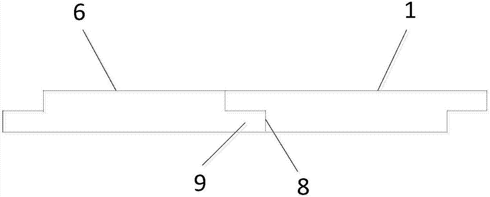
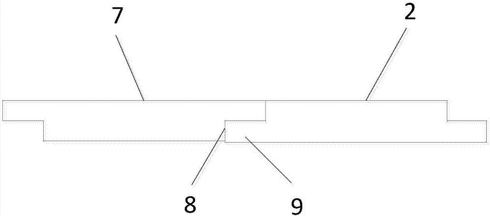
[0031] Such as Figure 1-4 Shown is a specific implementation of the sand-plastic floor that is easy to install. The length direction and width direction in this embodiment refer to the length direction and width direction of the ground in the room. Several sand-plastic floors are arranged in sequence so that...


PUM


Abstract

The invention relates to the technical field of building materials, in particular to a sand-plastic floor convenient to mount. The sand-plastic floor comprises a first sand-plastic floor body and a second sand-plastic floor body which are connected in the length direction, and further comprises the first sand-plastic floor body and a third sand-plastic floor body which are connected in the width direction as well as the second sand-plastic floor body and a fourth sand-plastic floor body which are connected in the width direction. A pair of edges of the first sand-plastic floor body in the length direction is arranged to be a vertical edge and an oblique edges correspondingly, and a pair of edges of the second sand-plastic floor body in the length direction are arranged to be a vertical edge and an oblique edge correspondingly. The vertical edge and the oblique edge of the first sand-plastic floor body are each provided with at least one sliding groove provided with a plurality of protruding parts, and the vertical edge and the oblique edge of the second sand-plastic floor body are each provided with at least one sliding block matched with the corresponding sliding groove. A pair ofedges of the first groove sand-plastic floor body, the second sand-plastic floor body, the third sand-plastic floor body and the fourth sand-plastic floor body in the width direction are arranged tobe mounting grooves and convex blocks correspondingly. According to the sand-plastic floor convenient to mount, every two adjacent floor bodies are firmly connected in the horizontal direction and thevertical direction, and after long-term using, firm connection can also be guaranteed even if slight deformation occurs.

Description

technical field [0001] The invention relates to the technical field of building materials, in particular to an easy-to-install sand-plastic floor. Background technique [0002] The existing floor paving method is generally to bond two adjacent floors together by concrete or glue, and in order to ensure the firmness of the bonding, the amount of concrete or glue used is large, so that after the floor paving is completed , the excess concrete or glue will solidify on the surface of the floor, which will bring a lot of inconvenience to the later cleaning. In order to solve the above technical problems, Chinese patent document CN104675079A discloses a wood-plastic floor, including: an upper layer containing the surface and a lower layer containing the bottom surface, the lower layer of the wood-plastic floor has a tenon set downward, and the side end of the tenon near the outside of the floor is provided with The first buckle action part, the other side end of the tenon is prov...

Claims


Application Information

Patent Timeline
Patent Type & Authority Applications(China)
IPC IPC(8): E04F15/02
CPCE04F15/02038E04F2201/022E04F2201/023E04F2201/026E04F2201/043
Inventor 秦升益
Owner BEIJING RECHSAND SCI & TECH GRP
Learn More