Spray dryer

A spray dryer and drying tower technology, which is applied in spray evaporation, evaporator adjustment/control, evaporator accessories, etc., can solve the problem of inability to actively adjust the material particle size and material collection ratio relationship, and the material collector cannot quantitatively collect materials. Problems such as troublesome material collection, to achieve the effect of convenient and fast adjustment, avoid weighing and packaging, and simple structure

Inactive Publication Date: 2018-04-06
CHENGDU YITIAN TECH CO LTD
View PDF0 Cites 2 Cited by
  • Summary
  • Abstract
  • Description
  • Claims
  • Application Information

AI Technical Summary

Problems solved by technology

However, in the existing above-mentioned second collection method, the position and the size of the air outlet provided on the drying tower are fixed, so it cannot be adjusted according to different materials, and its versatility is not strong; in addition , and it is impossible to actively adjust the particle size of the material in the two collection devices and the collection ratio of the material
[0004] Moreover, the material receiving device of the existing spray dryer is only a material collector. After the material collection is completed, the material in the collector needs to be weighed and packaged again. The material collector cannot quantitatively collect the material, which will increase the subsequent one. Work procedures that make material collection cumbersome

Method used


Image

  • Spray dryer
  • Spray dryer
  • Spray dryer

Examples


Embodiment

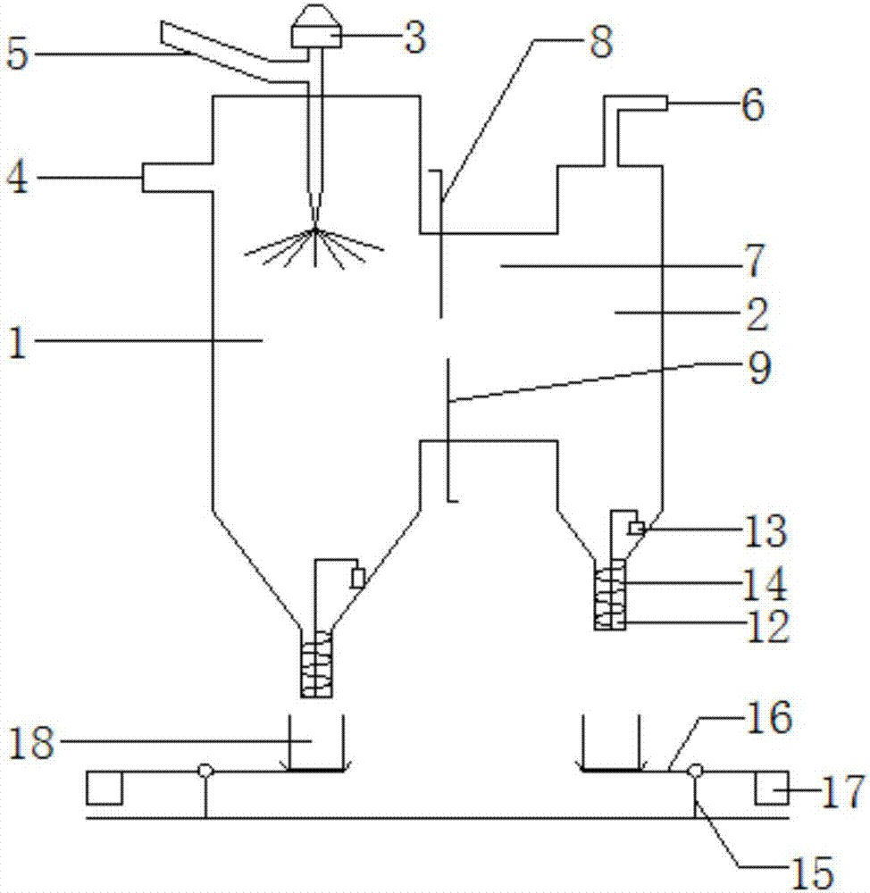
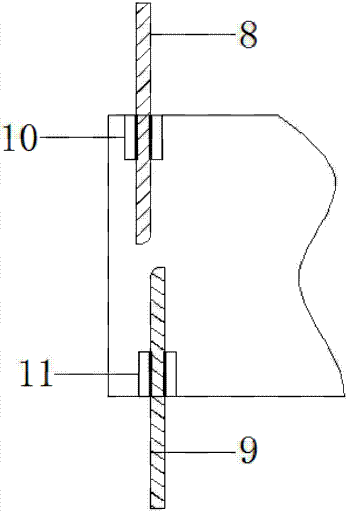
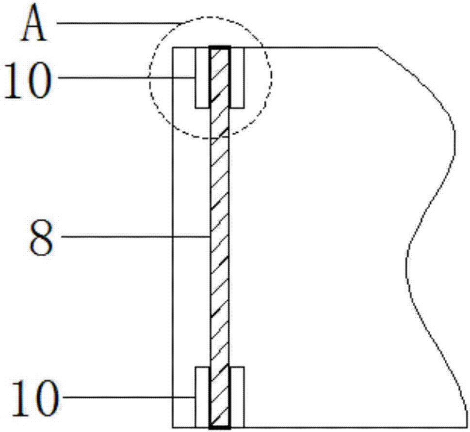
[0034] Such as Figure 1-Figure 8As shown, in order to achieve the above object, the technical solution adopted in the present invention is: a spray dryer, comprising a drying tower 1, a cyclone separator 2, a high-speed centrifugal atomizer 3; the top of the drying tower 1 is provided with a hot air inlet 4 After the high-speed centrifugal atomizer 3 passes through the top center of the drying tower 1, the nozzle of the high-speed centrifugal atomizer 3 is located at the top of the drying tower 1, and the high-speed centrifugal atomizer 3 is the same as the drying tower 1 The axis is set, the high-speed centrifugal atomizer 3 is provided with a feed inlet 5, and the top of the cyclone separator 2 is provided with an air outlet 6; the side wall of the drying tower 1 and the side wall of the cyclone separator 2 The side wall is provided with a chamber 7 communicated in the vertical direction, the chamber 7 is provided with a first dividing plate 8 vertically inserted into the c...


PUM


Abstract

The invention discloses a spray dryer, which comprises a drying tower, a cyclone separator, and a high-speed centrifugal atomizer; the top of the drying tower is provided with a hot air inlet, and the high-speed centrifugal atomizer passes through the center of the top of the drying tower. The nozzle is located at the top of the drying tower, and the high-speed centrifugal atomizer is set concentrically with the drying tower. The high-speed centrifugal atomizer is provided with a feed port, and the top of the cyclone separator is provided with an air outlet; the side wall of the drying tower The side wall of the cyclone separator is provided with a chamber connected in the vertical direction, the chamber is provided with a first partition vertically inserted into the chamber from the top, and the chamber is provided with a vertically inserted chamber from the bottom. The second partition, by adjusting the position between the first partition and the second partition, the position of the air outlet on the drying tower and the size of the air outlet can be adjusted, so that the particle size of the material discharged from the chamber with the airflow can be adjusted. The size and the amount of material discharge can be flexibly controlled, and the invention is also provided with a weighing system.

Description

technical field [0001] The invention relates to the field of drying equipment, in particular to a spray dryer. Background technique [0002] The spray dryer is a kind of equipment that can achieve drying and granulation at the same time. The working principle is that the air is filtered and heated, and enters the air distributor on the top of the dryer, and the hot air enters the drying chamber evenly in a spiral shape. The feed liquid passes through the high-speed centrifugal atomizer at the top of the tower, and is sprayed into very fine mist-like liquid droplets, which can be dried into finished products in a very short time in contact with hot air. The finished product is continuously output from the bottom of the drying tower and the cyclone separator. [0003] For the existing spray dryer, there are generally two collection methods for the granulated and dried materials in the drying tower: the first one is to directly discharge the materials through the airflow from ...

Claims


Application Information

Patent Timeline
Patent Type & Authority Applications(China)
IPC IPC(8): B01D1/18B01D1/20B01D1/30
CPCB01D1/0082B01D1/18B01D1/20B01D1/30
Inventor 曹海燕杨波
Owner CHENGDU YITIAN TECH CO LTD
Why Eureka
Try Eureka