Photovoltaic microgrid system and control method thereof

A photovoltaic power generation system, photovoltaic technology, applied in the direction of photovoltaic power generation, AC network circuit, AC network load balancing, etc., can solve the problem of AC harmonics affecting the power grid and photovoltaic inverter, inability to apply photovoltaic panel power generation, and limited output power etc. to achieve smooth and stable output power, simple structure, and improved utilization

Inactive Publication Date: 2018-04-03
BYD CO LTD
View PDF5 Cites 16 Cited by
  • Summary
  • Abstract
  • Description
  • Claims
  • Application Information

AI Technical Summary

Problems solved by technology

[0004] However, because the energy storage system is connected to the AC side of the photovoltaic inverter, the system output power is limited by the rated power of the photovoltaic inverter, and cannot be applied to the situation where the power generated by the photovoltaic panel is greater than the rated power of the photovoltaic inverter. It will cause waste of photovoltaic energy; at the same time, when the energy storage system is connected to the AC side, it will affect the AC harmonics of the grid and photovoltaic inverter
In addition, for the charging and discharging control strategy of the above technology, since the battery needs to absorb the power generated during the photovoltaic power generation period, the capacity of the battery needs to be large to meet the requirements of energy storage

Method used


Image

  • Photovoltaic microgrid system and control method thereof
  • Photovoltaic microgrid system and control method thereof
  • Photovoltaic microgrid system and control method thereof

Examples


Embodiment Construction

[0018] The following describes in detail the embodiments of the present invention, examples of which are illustrated in the accompanying drawings, wherein the same or similar reference numerals refer to the same or similar elements or elements having the same or similar functions throughout. The embodiments described below with reference to the accompanying drawings are exemplary, and are intended to explain the present invention and should not be construed as limiting the present invention.

[0019] The photovoltaic microgrid system and the control method thereof according to the embodiments of the present invention are described below with reference to the accompanying drawings.

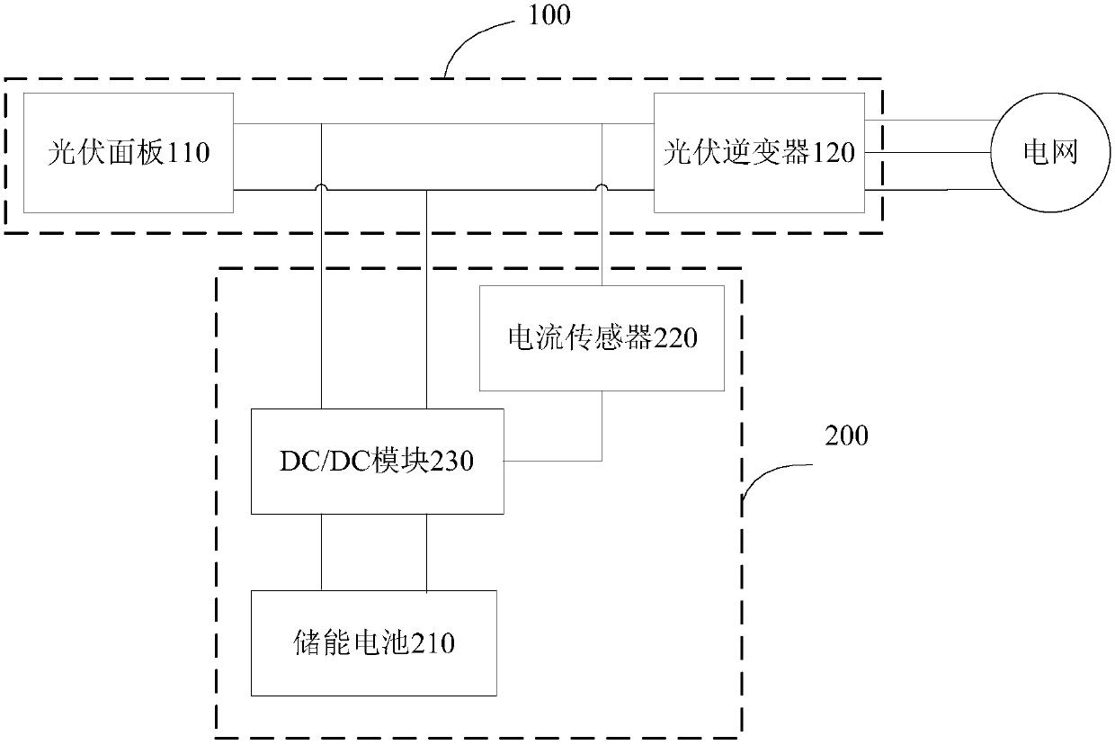
[0020] figure 2 It is a schematic structural diagram of a photovoltaic microgrid system according to an embodiment of the present invention. like figure 2 As shown, the photovoltaic microgrid system includes a photovoltaic power generation system 100 and a photovoltaic energy storage system 200...


PUM


Abstract

The invention discloses a photovoltaic microgrid system and a control method thereof. The photovoltaic microgrid system comprises a photovoltaic power generation system, and a photovoltaic energy storage system. The photovoltaic power generation system comprises a photovoltaic panel and a photovoltaic inverter. The photovoltaic energy storage system comprises an energy storage battery, a current sensor and a DC / DC module. The first end of the DC / DC module is connected with the output end of the photovoltaic panel. The second end of the DC / DC module is connected with the energy storage battery.The third end of the DC / DC module is connected with the direct-current side of the photovoltaic inverter through the current sensor. The DC / DC module is used for calculating the output power of the photovoltaic inverter according to the output voltage of the photovoltaic panel and the current of the direct-current side of the photovoltaic inverter, and adjusting the working state of the photovoltaic energy storage system according to the output power of the photovoltaic inverter, the output voltage of the photovoltaic panel and the SOC of the energy storage battery. The system is simple in structure and good in autonomy. The alternating current harmonic of the power grid and the photovoltaic inverter is not influenced at all, and the energy utilization rate of the photovoltaic panel is high.

Description

technical field [0001] The invention relates to the technical field of photovoltaic microgrids, in particular to a photovoltaic microgrid system and a control method thereof. Background technique [0002] As a green energy, solar energy is an inexhaustible clean energy. Using solar energy for photovoltaic power generation can greatly reduce the dependence on fossil energy and reduce the environmental pollution caused by the use of fossil energy. However, photovoltaic power generation is affected by light and temperature. When the external environment changes rapidly, the photovoltaic power generation power will also change rapidly, so that the stable output power to the grid cannot be guaranteed. [0003] In order to make the output power of photovoltaic power generation smoother, an energy storage system can be added to the photovoltaic power generation system. At present, the photovoltaic energy storage system is connected to the AC side of the photovoltaic inverter and ...

Claims


Application Information

Patent Timeline
IPC IPC(8): H02J3/38H02J3/32
CPCH02J3/32H02J3/383Y02E10/56Y02E70/30
Inventor 杨荣春张超华孙嘉品尹韶文
Owner BYD CO LTD
Why Eureka
Try Eureka