
Light emitting diode current regulating drive circuit

A technology of light-emitting diodes and driving circuits, applied in electroluminescent light sources, light sources, electric light sources, etc., can solve the problems of high market price, low transmission speed, and high cost, and achieve the effect of reducing costs and improving modulation bandwidth

Pending Publication Date: 2018-03-30
深圳久屹光电有限公司
View PDF10 Cites 0 Cited by
  • Summary
  • Abstract
  • Description
  • Claims
  • Application Information

AI Technical Summary

Problems solved by technology

[0003] (RCLED: Resonant Cavity Light Emitting Diode), is a new light-emitting diode (LED) structure, which has the advantages of both traditional LED and vertical cavity surface laser (VCSEL); in view of these characteristics of RCLED, it also causes its The high market price, most of which are produced abroad, the low transmission speed and high cost of RCLED limit its wide use in the market, and also hinder the development of optical fiber communication

Method used


Image

  • Light emitting diode current regulating drive circuit
  • Light emitting diode current regulating drive circuit
  • Light emitting diode current regulating drive circuit

Examples


Embodiment Construction

[0015] The preferred embodiments of the present invention will be described in further detail below in conjunction with the accompanying drawings.

[0016] Such as figure 1 As shown, a light-emitting diode (LED) current regulation drive circuit provided by the present invention includes an LED, a second current-limiting resistor R2, a first current-limiting resistor R1, and a signal switch tube Q1; the anode of the LED is connected to the input power supply, The negative electrode of the LED is electrically connected to the input terminal of the signal switch tube Q1 through the second current limiting resistor R2; the output terminal of the signal switch tube Q1 is grounded; the signal input terminal of the signal switch tube Q1 is connected to the data signal (DATA); the first current limiting resistor R1 One end of the first current limiting resistor R1 is electrically connected to the negative electrode of the LED, and the other end of the first current limiting resistor R...


PUM


Abstract

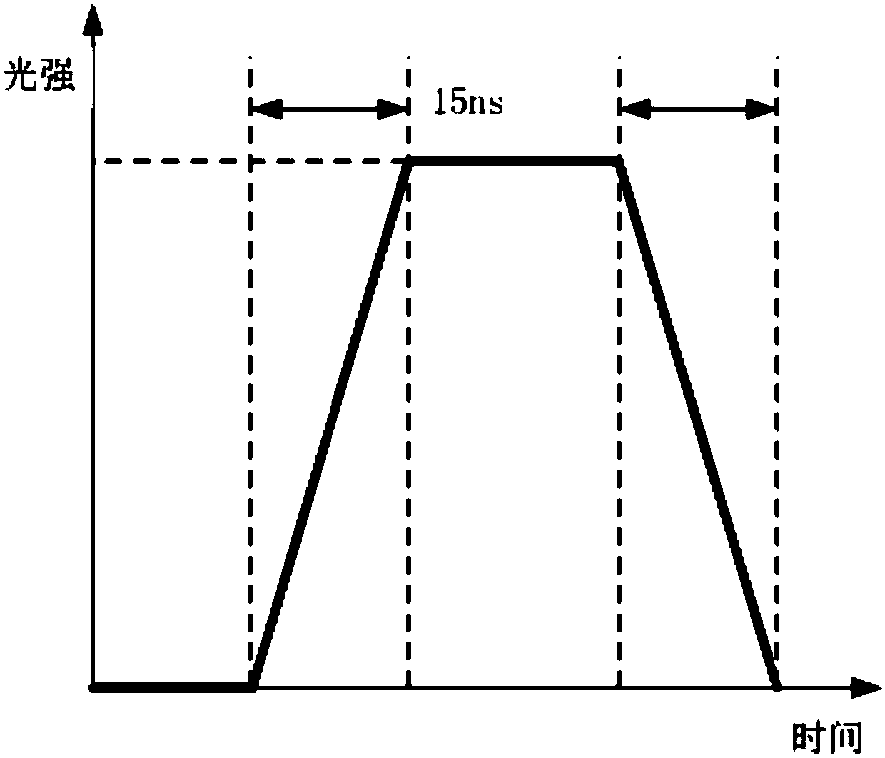
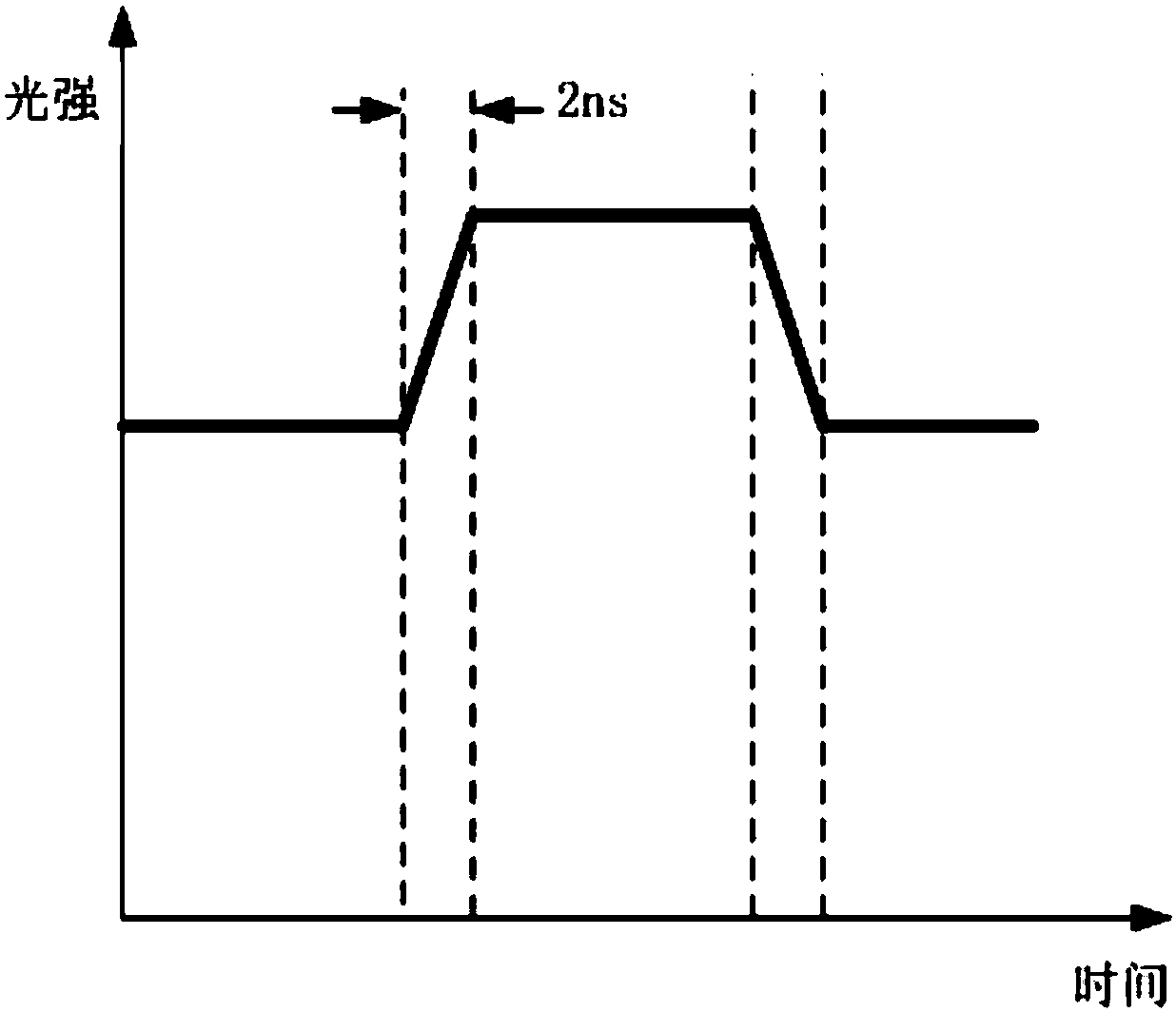
The invention discloses a light emitting diode current regulating drive circuit which comprises an LED (light emitting diode), a second current limiting resistor R2, a first current limiting resistorR1 and a signal switching tube Q1. A positive electrode of the LED is connected with an input power supply, a negative electrode of the LED is electrically connected with an input end of the signal switching tube Q1 through the second current limiting resistor R2, an output end of the signal switching tube Q1 is grounded, a signal input end of the signal switching tube Q1 is connected with data signals, one end of the first current limiting resistor R1 is electrically connected with the negative electrode of the LED, and the other end of the first current limiting resistor R1 is grounded. According to the LED current regulating drive circuit, the LED is incompletely switched off, the light intensity of the LED reaches the degree that light cannot be received, the LED is high in brightnessby increasing current flowing through the LED when the signal switching tube Q1 is on, and the LED emits slight light by decreasing the current flowing through the LED when the signal switching tube Q1 is off. Besides, the modulation bandwidth of a common LED can be increased, the circuit can be used for hundred-megabyte optical fiber communication, and the use cost of an optical communication module is greatly reduced.

Description

technical field [0001] The invention relates to the field of photoelectric conversion, in particular to a light-emitting diode current regulation drive circuit. Background technique [0002] At this stage, in short-distance optical fiber communication, the light source uses resonant cavity light-emitting diodes [0003] (RCLED: Resonant Cavity Light Emitting Diode), is a new light-emitting diode (LED) structure, which has the advantages of both traditional LED and vertical cavity surface laser (VCSEL); in view of these characteristics of RCLED, it also causes its The high market price, most of which are produced abroad, the low transmission speed and high cost of RCLED all limit its wide use in the market, and also hinder the development of optical fiber communication. Contents of the invention [0004] Based on the above-mentioned problems, the problem to be solved by the present invention is to provide a light-emitting diode current regulation drive circuit that utilize...

Claims


Application Information

Patent Timeline
Patent Type & Authority Applications(China)
IPC IPC(8): H05B33/08H05B44/00
CPCH05B45/00
Inventor 刘向宁
Owner 深圳久屹光电有限公司
Learn More