
Monitoring type radio data storage method

A technology for data storage and radio, applied in TV, color TV components, closed-circuit TV systems, etc., can solve the problems of poor selectivity, difficulty in ensuring the same selectivity and passband, and complicated tuning, so as to avoid waste.

Active Publication Date: 2018-03-30
东莞市声阳电子五金有限公司
View PDF3 Cites 12 Cited by
  • Summary
  • Abstract
  • Description
  • Claims
  • Application Information

AI Technical Summary

Problems solved by technology

High-amplified radios are more sensitive and powerful than direct-detection radios, but have poorer selectivity and more complicated tuning
To amplify the high-frequency signal received from the antenna by hundreds or even tens of thousands of times, generally several levels of high-frequency amplification are required, and each level of circuit has a resonant circuit. When the received frequency changes, the resonant circuit must be rebuilt. Adjustment, and it is difficult to ensure that the selectivity and passband are exactly the same after each adjustment. In order to overcome these shortcomings, almost all current radios use superheterodyne circuits

Method used


Image

  • Monitoring type radio data storage method
  • Monitoring type radio data storage method

Examples

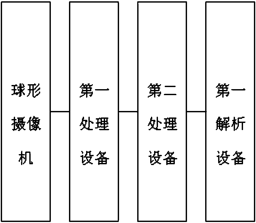
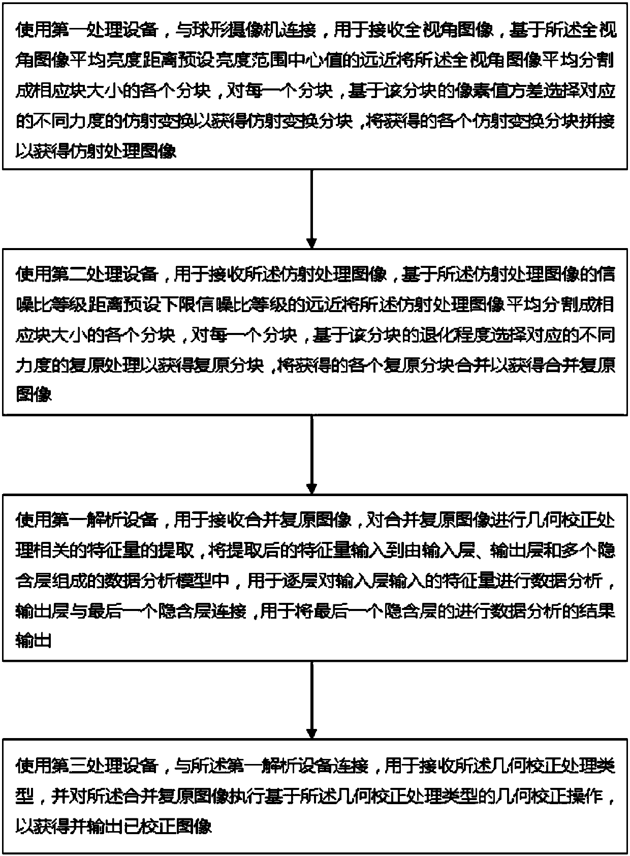

Embodiment Construction

[0024] The embodiment of the monitoring radio data storage method of the present invention will be described in detail below with reference to the accompanying drawings.

[0025] In order to overcome the above-mentioned deficiencies, the present invention sets up a monitoring radio data storage method, and the specific implementation scheme is as follows.

[0026] figure 1 It is a structural block diagram of a monitoring radio data storage system shown according to an embodiment of the present invention, the system includes: a first processing device, connected to a spherical camera, for receiving a full-view image, based on the average brightness distance of the full-view image The distance of the center value of the preset brightness range divides the full-view image into blocks of corresponding block sizes, and for each block, selects the corresponding affine transformation of different strengths based on the pixel value variance of the block to obtain The affine transform...


PUM


Abstract

The invention relates to a monitoring type radio data storage method. The method comprises the following steps: a first processing device is used for connection with a spherical camera for receiving afull-angle image, the full-range image is averagely segmented into blocks in sizes of corresponding blocks on the basis of the distance from the average brightness of the full-range image to a presetbrightness scope center value, for each block, based on a pixel value variance of the block, corresponding affine transformations with different strengths are selected so that affine transformation blocks are obtained, and the obtained affine transformation blocks are spliced so that an affine processed image is obtained.

Description

technical field [0001] The invention relates to the field of radios, in particular to a monitoring radio data storage method. Background technique [0002] The simplest radio is called a direct detector. However, the high-frequency radio signal obtained from the receiving antenna is generally very weak, and it is not suitable to send it directly to the detector. It is better to insert a high-frequency amplifier between the selection circuit and the detector to amplify the high-frequency signal. Even if a high-frequency amplifier has been added, the power of the detection output is usually only a few milliwatts, which is okay to listen to with headphones, but it is too small to use a speaker, so an audio amplifier is added after the detection output to drive the speaker. High-amplitude radios have higher sensitivity and higher power than direct-detection radios, but they are less selective and more complicated to tune. To amplify the high-frequency signal received from the...

Claims


Application Information

Patent Timeline
Patent Type & Authority Applications(China)
IPC IPC(8): H04N7/18H04N5/262H04N5/268H04N5/265H04B1/06
CPCH04B1/06H04N5/262H04N5/265H04N5/268H04N7/18
Inventor 秦广民
Owner 东莞市声阳电子五金有限公司
Learn More