
Display panel and display device

A display panel and display area technology, applied in semiconductor devices, electrical components, circuits, etc., can solve problems such as differences in display effects, achieve the effects of reducing differences, improving display effects, and reducing load gaps

Active Publication Date: 2018-03-30
WUHAN TIANMA MICRO ELECTRONICS CO LTD
View PDF4 Cites 13 Cited by
  • Summary
  • Abstract
  • Description
  • Claims
  • Application Information

AI Technical Summary

Problems solved by technology

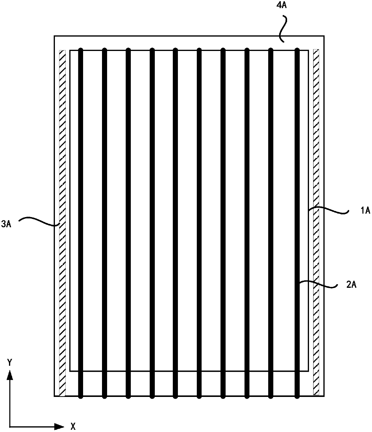
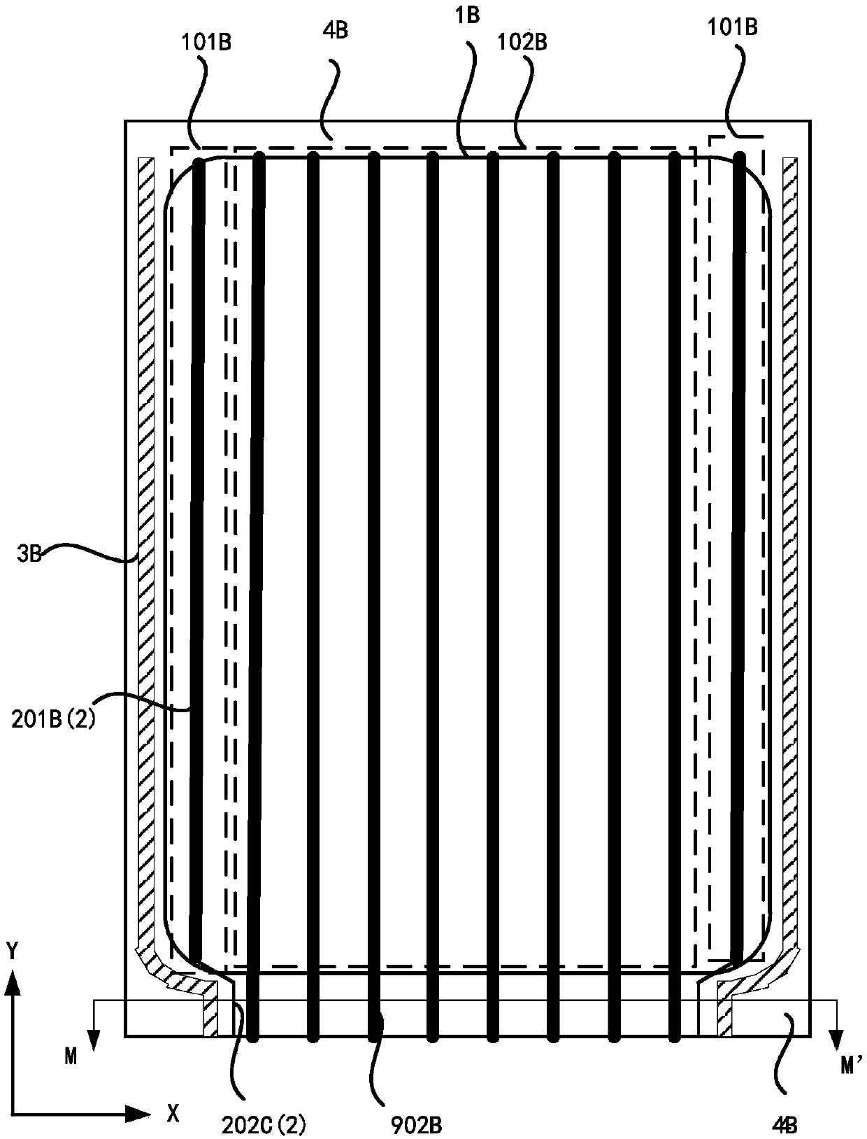
[0003] Embodiments of the present invention provide a display panel and a display device, which are used to solve the problem in the prior art that in the column direction of the display panel, the display area corresponding to the rounded corner is different from the display effect of other display areas.

Method used


Image

  • Display panel and display device
  • Display panel and display device
  • Display panel and display device

Examples


Embodiment Construction

[0032] In order to make the purpose, technical solutions and advantages of the embodiments of the present invention clearer, the technical solutions in the embodiments of the present invention will be clearly and completely described below in conjunction with the drawings in the embodiments of the present invention. Obviously, the described embodiments It is a part of embodiments of the present invention, but not all embodiments. Based on the embodiments of the present invention, all other embodiments obtained by persons of ordinary skill in the art without creative efforts fall within the protection scope of the present invention.

[0033] Terms used in the embodiments of the present invention are only for the purpose of describing specific embodiments, and are not intended to limit the present invention. As used in the embodiments of the present invention and the appended claims, the singular forms "a", "said" and "the" are also intended to include the plural forms unless th...


PUM


Abstract

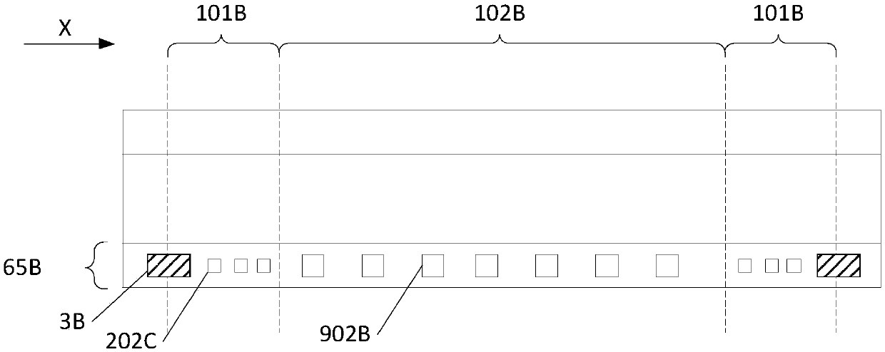
The embodiment of the invention provides a display panel and a display device. The display panel comprises a display area, a non-display area, a power source signal line and multiple positive pole blocks, wherein the display area is a rectangle provided with at least a fillet; the power source signal line is arranged along a row direction, stretches along a column direction, is electrically connected with a pixel unit on a corresponding column, and comprises the first part of alignment line in the display area and the second part of alignment line in the non-display area, and the first part ofalignment line and the source drain metal layer of a thin film transistor in the pixel unit are arranged on the same layer; the positive pole blocks are arranged on one side, which is far away from asubstrate base plate, of the thin film transistor; the second part of alignment line of a power source signal line in at least a fillet area and the positive pole block are arranged on the same layer, by the design, the line width of the second part of alignment line corresponding to the fillet area becomes large, and then the load gap of the power source signal line corresponding to the fillet area and the power source signal line corresponding to a non-fillet area is reduced, so that the display effect of the display panel is improved.

Description

technical field [0001] The present invention relates to the field of display technology, in particular to a display panel and a display device. Background technique [0002] With the development of science and technology, people have more and more diversified demands on the screen of the display device. Therefore, the display area of ​​the display panel is often designed in a shape other than a regular rectangle. For example, the display area is designed as a rounded rectangle. After adopting the above design, the circuits located in the non-display area (such as pixel drive unit, anti-static wiring, etc.) The space is occupied, for example, the circuit arranged along the edge of the rounded corner occupies the setting space of the power signal line corresponding to the rounded corner in the non-display area in the row direction, so that the power signal line corresponding to the rounded corner is in the non-display area In order to avoid the electrical connection between t...

Claims


Application Information

Patent Timeline
Patent Type & Authority Applications(China)
IPC IPC(8): H01L27/12H01L27/32
CPCH01L27/124H10K59/131
Inventor 张春鹏
Owner WUHAN TIANMA MICRO ELECTRONICS CO LTD
Learn More