Coiling type high-temperature stretching test clamp for sheet-shaped material
A sheet material, tensile test technology, applied in the direction of analyzing materials, using stable tension/pressure testing material strength, measuring devices, etc., can solve the problem that the real length change cannot be measured, and the normal temperature tensile test fixture cannot be used normally and other problems to achieve the effect of eliminating experimental errors
- Summary
- Abstract
- Description
- Claims
- Application Information
AI Technical Summary
Problems solved by technology
Method used
Image
Examples
specific Embodiment approach 1
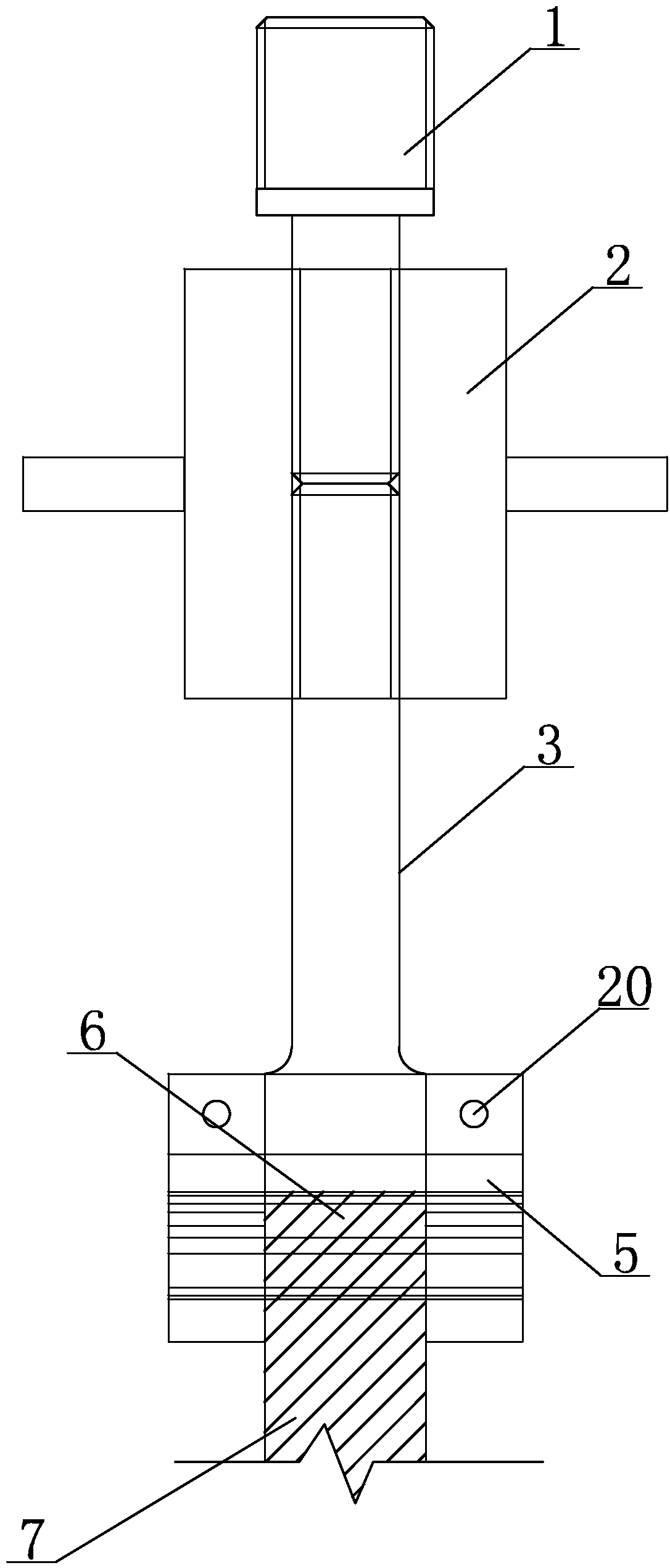
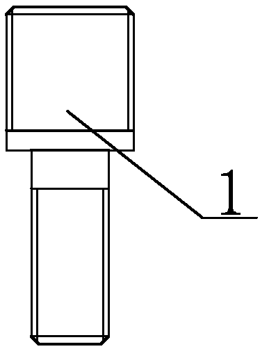
[0022] Specific implementation mode one: combine Figure 1 to Figure 16 Describe this embodiment mode, a kind of sheet-shaped material winding type high-temperature tensile test fixture of this embodiment mode, it comprises upper clamping body, lower clamping body and test piece 7, the upper end of upper clamping body and the lower end of lower clamping body are all connected with tensile The tensile testing machine is connected, and the lower end of the upper clamp body and the upper end of the lower clamp body are connected through the test piece 7;
[0023] The upper clamp body includes the upper clamp A connecting rod 1, the upper clamp length adjustment valve 2, the upper clamp B connecting rod 3, the upper clamp clamping end 5 and the upper clamp winding end 6, the upper clamp A connecting rod 1 and the upper clamp B connecting rod 3 are connected through the length adjustment valve 2 of the upper fixture, the clamping end 5 of the upper fixture is connected with the con...
specific Embodiment approach 2
[0027] Specific implementation mode two: combination Figure 12 Describe this embodiment, the upper clamp length adjustment valve 2 and the lower clamp length adjustment valve 9 of this embodiment have the same structure, the upper clamp length adjustment valve 2 includes a cylinder 2-1 and two handles 2-2, two handles 2- 2. It is fixedly installed on the outer wall of the cylinder body 2-1. The cylinder body 2-1 is provided with an internal thread 2-3 in the opposite direction of rotation; the connecting rod 1 of the upper fixture A and the connecting rod 3 of the upper fixture B are equipped with Internal thread 2-3 matched external thread. Such setting makes it convenient to adjust the vertical lengths of the upper fixture A connecting rod 1 and the upper fixture B connecting rod 3 by pulling the two handles 2-2 during actual use, making the use more flexible and the operation more accurate. Other compositions and connections are the same as in the first embodiment.
specific Embodiment approach 3
[0028] Specific implementation mode three: combination Figure 12 Describe this embodiment, the upper clamping end 5 of this embodiment includes two upper clamping pieces, the two upper clamping pieces are oppositely arranged, and each upper clamping piece all includes an upper clamping block 5-1 and an upper clamping piece Holding rod 5-2, the upper clamping rod 5-2 is installed on the upper end of the upper clamping block 5-1 and is integrated with the upper clamping block 5-1, and the middle part of the upper clamping block 5-1 is provided with three fan-shaped The upper through hole 5-3; the clamping end 12 of the lower clamp includes two lower clamping parts, the two lower clamping parts are arranged oppositely, and each lower clamping part includes a lower clamping block 12-1 and a lower clamping rod 12-2, the lower clamping rod 12-2 is installed on the upper end of the lower clamping block 12-1 and is integrated with the lower clamping block 12-1, and the middle part of...
PUM
 Abstract
Description
Claims
Application Information
 - Generate Ideas
- Intellectual Property
- Life Sciences
- Materials
- Tech Scout
- Unparalleled Data Quality
- Higher Quality Content
- 60% Fewer Hallucinations
Browse by: Latest US Patents, China's latest patents, Technical Efficacy Thesaurus, Application Domain, Technology Topic, Popular Technical Reports.
© 2025 PatSnap. All rights reserved.Legal|Privacy policy|Modern Slavery Act Transparency Statement|Sitemap|About US| Contact US: help@patsnap.com


