


Quick Research
Generate reliable direction feasibility study reports for your R&D in just a few steps.

Technical Q&A
Discover and master advanced knowledge NOW. Basics, ideas, possibilities, all at once.

Find Solutions
As an expert in R&D theories, this can generate solutions to your technical problems instantly.

Evaluate Feasibility
Analyze your overall solution with one click, know your potential R&D risks in advance.

Monitor Landscape
Get weekly tech updates, stay abreast of the latest tech innovations and key insights.
Novel industrial camera shooting moving mechanism
A technology of moving mechanism and camera, applied in the direction of supporting machine, mechanical equipment, machine/stand, etc., can solve the problem of unable to achieve position adjustment, unable to achieve 360° shooting of items, etc., to avoid unclear camera and avoid rotating motion. Effect
- Summary
- Abstract
- Description
- Claims
- Application Information
AI Technical Summary
Problems solved by technology
Method used
Image


Examples
Embodiment 1
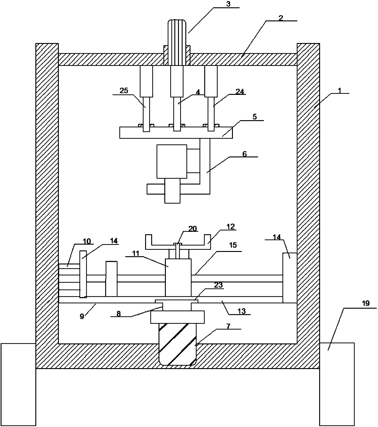
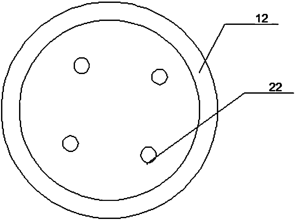
[0026] A new type of industrial camera camera movement mechanism, including a bracket 1 and a top beam 2 arranged on the bracket 1, a cylinder 3 is arranged in the middle of the top beam 2, and one end of a first telescopic rod 4 is connected to the cylinder 3. The other of the first telescopic rod 4 is connected with a moving plate 5, the lower surface of the moving plate 5 is provided with an L-shaped camera holder 6, and the bottom wall of the support 1 is provided with a rotating motor 7, and the rotating motor 7 is connected with a fixed block 8, and the fixed block 8 is fixedly connected with the linear ball screw guide rail 9, and a steering motor 10 is arranged on one side of the linear ball screw guide rail 9, and the linear ball screw guide rail 9 is provided with A slider 11, on which a support plate 12 is fixedly arranged.
[0027] Put the object to be photographed on the support plate 12, drive the first telescopic rod 4 to reciprocate up and down through the cyli...
Embodiment 2
[0029] On the basis of Embodiment 1, the linear ball screw guide rail 9 includes a bottom plate 13 , baffles 14 arranged at both ends of the bottom plate 13 and a movable assembly 15 arranged between the two baffles 14 . Two baffle plates 14 are set to prevent the movement from derailing.
Embodiment 3
[0031] On the basis of Embodiment 2, the movable assembly 15 includes a first guide rail 16, a second guide rail 17, a screw mandrel 18 and a slider 11, and the first guide rail 16 and the first guide rail 16 are arranged at intervals between the two baffle plates 14. The second guide rail 17 is provided with a screw rod 18 between the first guide rail 16 and the second guide rail 17, and one end of the screw rod 18 extends to the outside of the baffle plate 14 and is connected with a steering motor 10. A slide block 11 is movably arranged on the first guide rail 16 , the second guide rail 17 and the screw mandrel 18 . Slide block 11 is meshed with screw mandrel 18. The movement of the screw rod 18 drives the slider 11 to move, so that the slider 11 moves on the track of the first guide rail 16 and the second guide rail 17, so that the movement of the slider 11 can be made smoother.
PUM
 Abstract
Description
Claims
Application Information
 - R&D Engineer
- R&D Manager
- IP Professional
- Industry Leading Data Capabilities
- Powerful AI technology
- Patent DNA Extraction
Browse by: Latest US Patents, China's latest patents, Technical Efficacy Thesaurus, Application Domain, Technology Topic, Popular Technical Reports.
© 2024 PatSnap. All rights reserved.Legal|Privacy policy|Modern Slavery Act Transparency Statement|Sitemap|About US| Contact US: help@patsnap.com