Power conversion device and its automatic tuning method
A power conversion device, automatic tuning technology, applied in the direction of AC motor control, electrical components, control systems, etc., can solve problems such as difficulty in setting, and achieve the effect of high torque
- Summary
- Abstract
- Description
- Claims
- Application Information
AI Technical Summary
Problems solved by technology
Method used
Image

Examples
Embodiment 1
[0044] Embodiment 1 relates to detection of mutual inductance M in consideration of magnetic saturation based on V / f control.
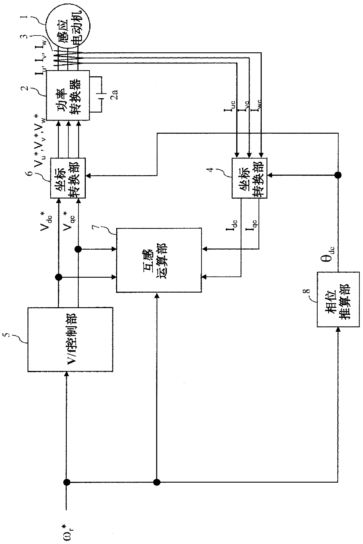
[0045] figure 1 A configuration diagram showing a power conversion device according to Embodiment 1 of the present invention.
[0046] The induction motor 1 generates torque by a magnetic flux generated by a current component of a magnetic flux axis (d axis) and a current component of a torque axis (q axis) perpendicular to the magnetic flux axis.
[0047] Power converter 2 outputs and three-phase AC voltage command value V u * , V v * , V w * In direct proportion to the voltage value, adjust the output voltage value and rotation frequency value of the induction motor 1.
[0048] The DC power supply 2 a supplies a DC voltage to the power converter 2 .
[0049] The current detector 3 outputs the three-phase AC current I of the induction motor 1 u , I v , I w The detection value of I uc , I vc , I wc . The current detector 3 can also dete...
Embodiment 2
[0074] Example 2 involves generating tables of mutual inductance and field current.
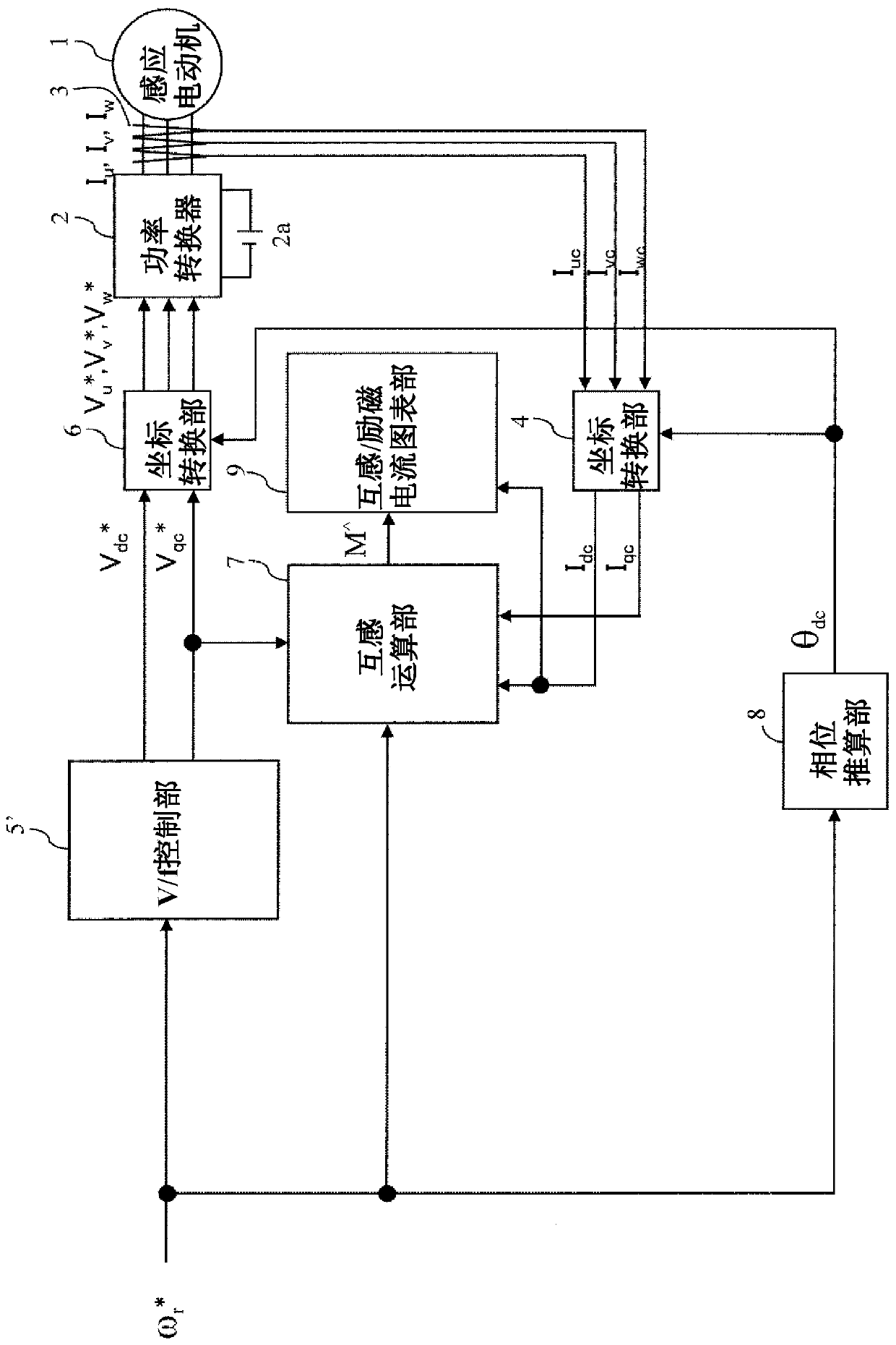
[0075] image 3 It is a configuration diagram of a power conversion device according to Embodiment 2 of the present invention.
[0076] In Embodiment 1, the ratio of the output voltage to the output frequency of the V / f control unit (hereinafter referred to as V / f ratio) was set to a fixed value, but in this embodiment, the V / f ratio is changed in multiple steps.
[0077] In the figure, symbols 1~4, 6~8 and figure 1 of the same.
[0078] Figure 4 It is a block diagram of the V / f control part 5'.
[0079] In the V / f control unit 5', the V / f ratio (V / f_gain) that changes in multiple stages is set as the variable 5'a, and the speed command value ω r * Multiply, and output the q-axis voltage command value V qc * . In addition, for the d-axis voltage command value V dc * The output is set to zero at the constant 5'b.
[0080] exist Figure 5 An example of the output signal of the var...
Embodiment 3
[0093] Figure 8 It is a configuration diagram of a power conversion device according to Embodiment 3 of the present invention.
[0094] Embodiment 1 involves estimating mutual inductance M, embodiment 2 involves generating a table of mutual inductance and excitation current, and embodiment 3 applies the table generated in embodiment 2 to a power conversion device based on speed sensorless vector control.
[0095] Figure 8 Among them, symbols 1~4, 6, 8 and figure 1 of the same.
[0096] The speed estimation unit 10 based on the q-axis voltage command value V qc *** , q-axis current detection value I qc , output frequency value ω 1 * and the electrical constant of the induction motor 1 (R 1 , R 2 ') and the d-axis secondary magnetic flux command value φ of the d-axis current and magnetic flux command setting unit 13 2d * , output the estimated speed value ω of the induction motor 1 r ^ .
[0097] The slip frequency calculation unit 11 is based on the current comm...
PUM
 Abstract
Description
Claims
Application Information
 - R&D
- Intellectual Property
- Life Sciences
- Materials
- Tech Scout
- Unparalleled Data Quality
- Higher Quality Content
- 60% Fewer Hallucinations
Browse by: Latest US Patents, China's latest patents, Technical Efficacy Thesaurus, Application Domain, Technology Topic, Popular Technical Reports.
© 2025 PatSnap. All rights reserved.Legal|Privacy policy|Modern Slavery Act Transparency Statement|Sitemap|About US| Contact US: help@patsnap.com