
Device for presenting assistance images to driver, and method therefor

An image and image conversion technology, which is applied in the field of display control, can solve problems such as deterioration of visibility, and achieve the effect of eliminating unnaturalness and suppressing the deterioration of visibility

Inactive Publication Date: 2018-03-27
DENSO CORP
View PDF4 Cites 3 Cited by
  • Summary
  • Abstract
  • Description
  • Claims
  • Application Information

AI Technical Summary

Problems solved by technology

However, in the above-mentioned composite image, there is a problem that when there is an object in the overlapping image area, there is a concern about the deterioration of visibility related to the object.

Method used


Image

  • Device for presenting assistance images to driver, and method therefor
  • Device for presenting assistance images to driver, and method therefor
  • Device for presenting assistance images to driver, and method therefor

Examples


no. 1 approach

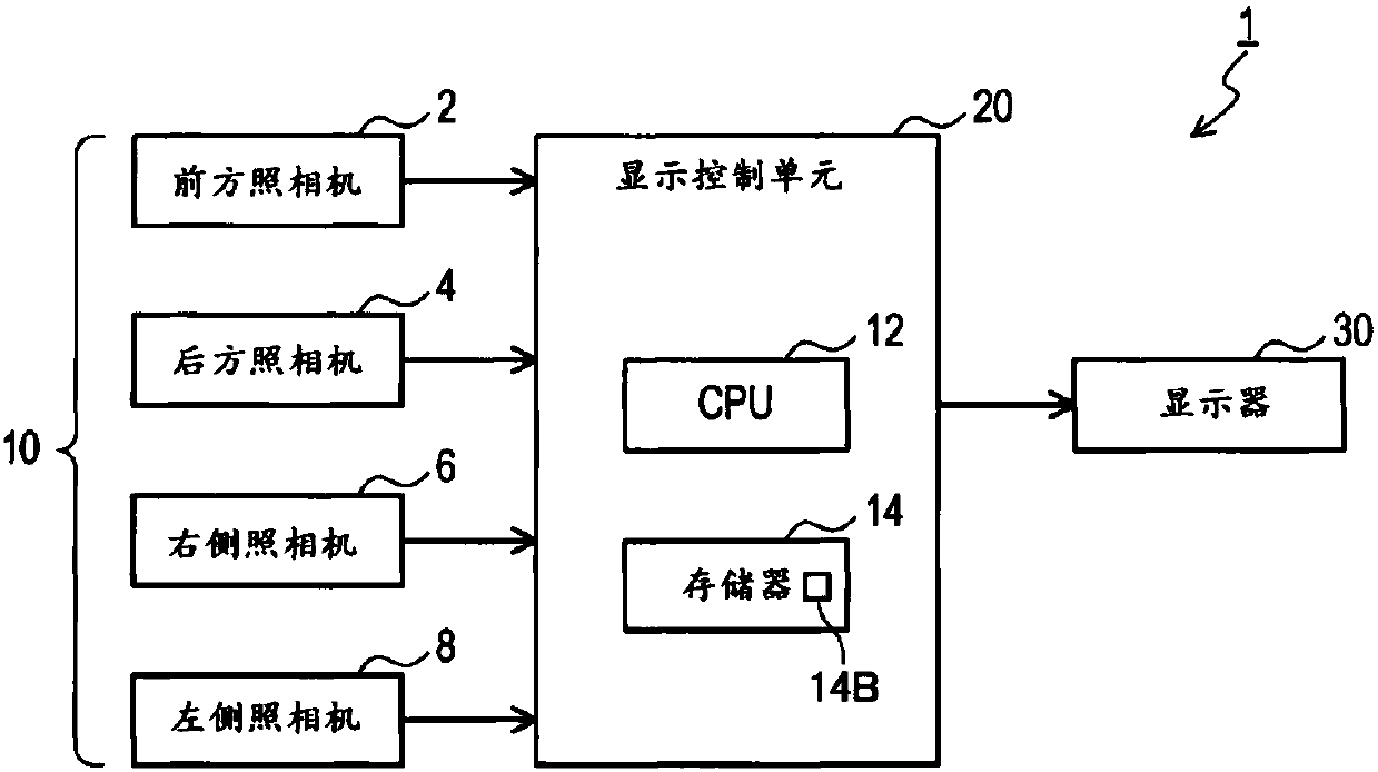
[0027] figure 1 The illustrated vehicle-mounted display control device 1 includes a plurality of cameras 10 , a display control unit 20 , and a display 30 . In addition, although not shown, the in-vehicle display control device 1 is configured to be connected to an in-vehicle local area network (hereinafter referred to as "in-vehicle LAN"), and to communicate with other electronic control units (hereinafter referred to as "in-vehicle LAN") connected to the in-vehicle LAN. Vehicle information such as detection information of various sensors is shared among "ECUs". In the following description, a vehicle equipped with these components is referred to as an own vehicle.

[0028] In addition, in this embodiment, the display control unit 20 is a processing device that processes image data captured by a plurality of cameras 10 (described later).

[0029] In addition, the in-vehicle LAN is a local area network provided inside the vehicle. For example, using the well-known CAN (Cont...


PUM


Abstract

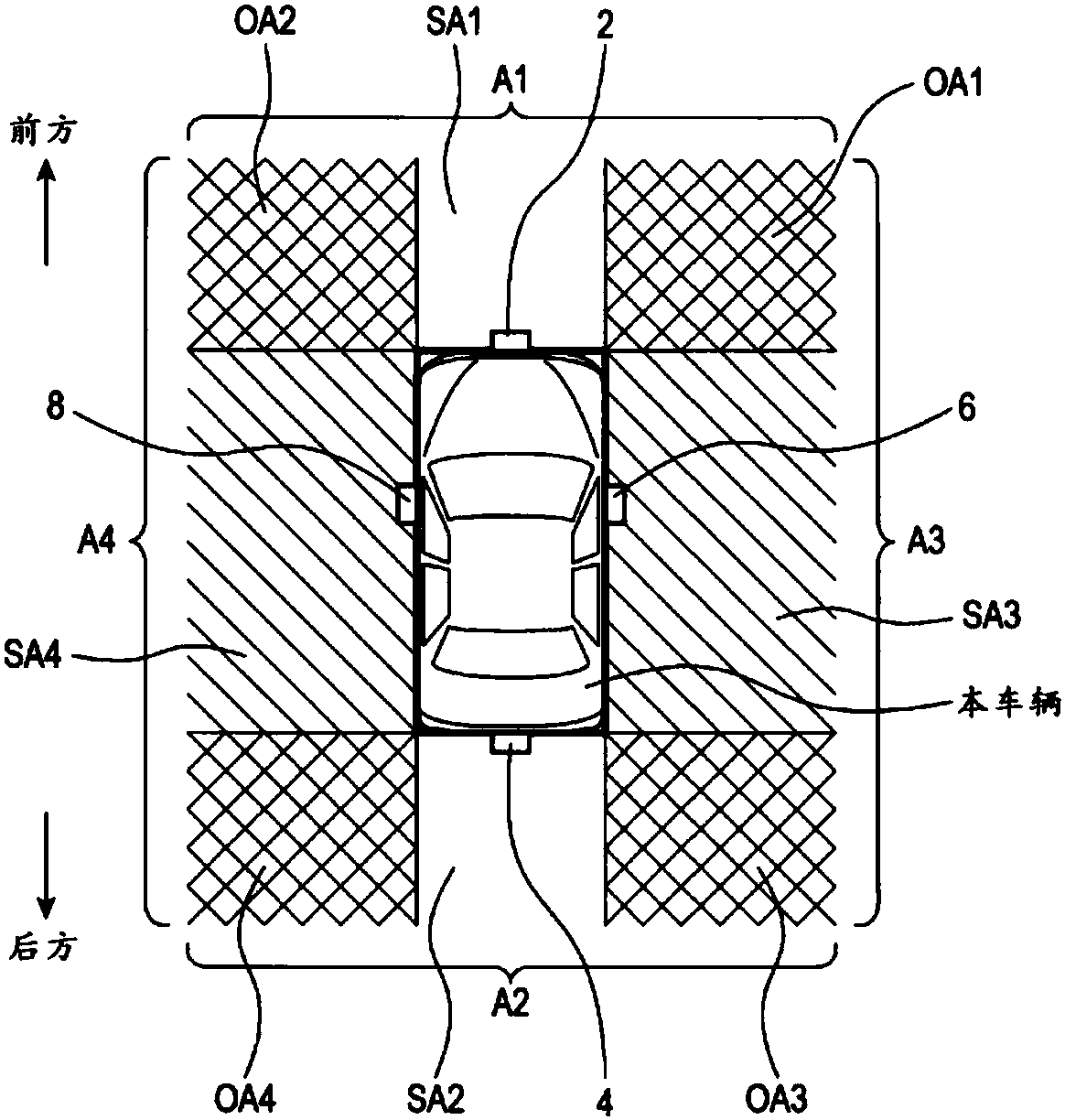
An image recognition unit (21) recognizes objects within each of a plurality of captured images of a plurality of imaging devices which respectively image each of a plurality of imaging regions aroundthe periphery of a vehicle which partially overlap. In cases when an imaging region including a recognized object is an overlapping region capable of being imaged by either of two imaging devices, animage synthesis unit (23) generates a synthesized image obtained by respectively converting each captured image into an image viewed from a virtual viewpoint, partially overlapping the respective converted images, and joining the respective converted images together. When generating the image obtained by partially overlapping and joining together the respective converted images, the image synthesis unit (23) uses a preset blend ratio to synthesize sections of the respective converted images in an overlapping image region where the respective converted images overlap. An image setting unit (24) sets, on the basis of object recognition results, the blend ratio for the sections of the respective converted images in the overlapping image region. A driving assistance image synthesized using the blend ratio set by the image setting unit (24) is outputted to a display device.

Description

technical field [0001] The present invention relates to a display control technology for providing driving assistance images to a driver of a vehicle, and more particularly relates to mounting a plurality of imaging devices on a vehicle so as to capture overlapping imaging areas around the vehicle, based on image data from these plurality of imaging devices Provides display control technology for driving assistance images. Background technique [0002] In conventional on-vehicle display control, it is known to use a plurality of on-vehicle cameras to take pictures of the partially overlapping shooting areas around the vehicle, and to connect the converted images of these multiple captured images to generate a display image, and then display the image. A technology that outputs images to on-board displays as driving assistance images. [0003] For example, a plurality of captured images are converted into bird's-eye images and these bird's-eye images are connected to generat...

Claims


Application Information

Patent Timeline
Patent Type & Authority Applications(China)
IPC IPC(8): G06T1/00B60R1/00G06T5/50G08G1/16H04N7/18
CPCG08G1/0962H04N7/181G06T11/00B60R2300/307B60R2300/602B60R2300/8093G06V20/58B60R1/27H04N7/18G06V20/56G06T5/50B60R2300/105B60R2300/303B60R2300/802B60W50/14B60W2050/146G06T2207/20221
Inventor 横田昇幸
Owner DENSO CORP
Learn More