Base plate with bumpy part and manufacturing method of the base plate
A manufacturing method and a technology of concave and convex parts, applied to the device for coating liquid on the surface, the input/output process of data processing, instruments, etc., can solve the complicated manufacturing method, the deterioration of the total light transmittance, and the haze of the transparent resin layer Value degradation and other problems, to achieve the effect of suppressing the Newton ring phenomenon, preventing the degradation of visibility, and improving the visibility
- Summary
- Abstract
- Description
- Claims
- Application Information
AI Technical Summary
Problems solved by technology
Method used
Image
Examples
Embodiment 1 to 3
[0100] Figure 7 (A) represents embodiment 1, Figure 7 (B) represents embodiment 2, Figure 7 (C) shows Example 3. Figure 7 It shows the measurement pattern obtained by measuring the concavo-convex pattern formed on the surface of the resin layer of each Example with a non-contact three-dimensional shape measuring device.
[0101] Figure 8 with Figure 7 (A) The same range represents the size of the concave-convex pattern of Example 1, the horizontal axis is the distance on the surface of the resin layer, and the vertical axis is the height dimension of the concave-convex surface. exist Figure 8 In , the numbered scale on the horizontal axis is 0.2 mm, whereas the numbered scale on the vertical axis is 0.1 μm. Figure 7 The ratio of the aspect ratio of the measured pattern to the Figure 8 Same, the actual concavo-convex pattern that forms on the surface of the resin layer of embodiment 1,2,3 and Figure 7 The image shown is smooth enough.
[0102] exist Figure ...
Embodiment 4 and 5
[0112] Figure 9 It is a diagram showing Example 4, (A) is a diagram showing a measurement pattern obtained by measuring a concavo-convex pattern formed on the surface of a resin layer by a non-contact three-dimensional shape measuring instrument, and (B) is the same as (A) A line graph representing the dimensions of the bump pattern. Figure 10 It is a figure showing Example 5, (A) is a figure showing the measurement pattern obtained by measuring the concavo-convex pattern formed on the surface of the resin layer by a non-contact three-dimensional shape measuring instrument, (B) is the same as (A) A line graph representing the dimensions of the bump pattern.
[0113] Figure 9 shown in Example 4 and Figure 10 Combinations of resins used in Example 5 shown with Figure 7 (A) and Figure 8 Example 1 shown is the same.
[0114] Also in Example 4 and Example 5, substantially hexagonal divided regions 22 a are regularly arranged, and each divided region 22 a has a smooth co...
Embodiment 6 to 8
[0117] Figure 11 (A) represents embodiment 6, Figure 11 (B) represents embodiment 7, Figure 11 (C) shows Example 8. Figure 11 It shows the measurement pattern obtained by measuring the concavo-convex pattern formed on the surface of the resin layer of each Example with a non-contact three-dimensional shape measuring device. Figure 11 The aspect ratio of the image map and Figure 7 to Figure 10 The embodiments shown are the same.
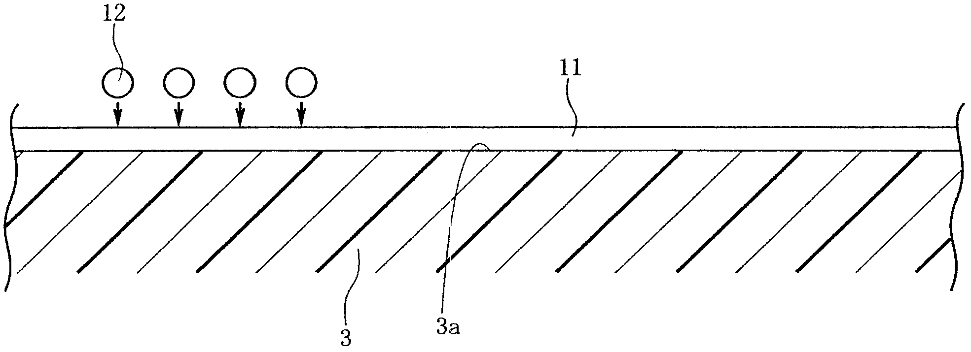
[0118] Figure 11 The examples shown all use resin A shown in Table 1 as the first resin 11 to form the base resin layer, and use resin B as the second resin 12 to form the base resin layer. Figure 6 The shown pattern of dots 21 feeds the second resin 12 .
[0119] exist Figure 11 In the examples (A), (B), and (C), the resin supply amount (volume) per unit area of the opposing surface 3 a of the lower sensing substrate 3 is different from each other to form a concave-convex pattern on the resin layer. exist Figure 11 In Example 6 s...
PUM
| Property | Measurement | Unit |
|---|---|---|
| Opening diameter | aaaaa | aaaaa |
| Centerline average roughness | aaaaa | aaaaa |
| Diameter | aaaaa | aaaaa |
Abstract
Description
Claims
Application Information
 - R&D
- Intellectual Property
- Life Sciences
- Materials
- Tech Scout
- Unparalleled Data Quality
- Higher Quality Content
- 60% Fewer Hallucinations
Browse by: Latest US Patents, China's latest patents, Technical Efficacy Thesaurus, Application Domain, Technology Topic, Popular Technical Reports.
© 2025 PatSnap. All rights reserved.Legal|Privacy policy|Modern Slavery Act Transparency Statement|Sitemap|About US| Contact US: help@patsnap.com


