Automatic toilet flushing system

Technology of a flusher, actuator, applied in the direction of water supply installations, flushing equipment with water tanks, construction

Inactive Publication Date: 2018-03-27
弗兰克法伯
View PDF8 Cites 0 Cited by
  • Summary
  • Abstract
  • Description
  • Claims
  • Application Information

AI Technical Summary

Problems solved by technology

[0005] The purpose of the present invention is to propose an economical, high-performance and ergonomic solution to the problems of odor and water consumption associated with toilets

Method used


Image

  • Automatic toilet flushing system
  • Automatic toilet flushing system
  • Automatic toilet flushing system

Examples


Embodiment Construction

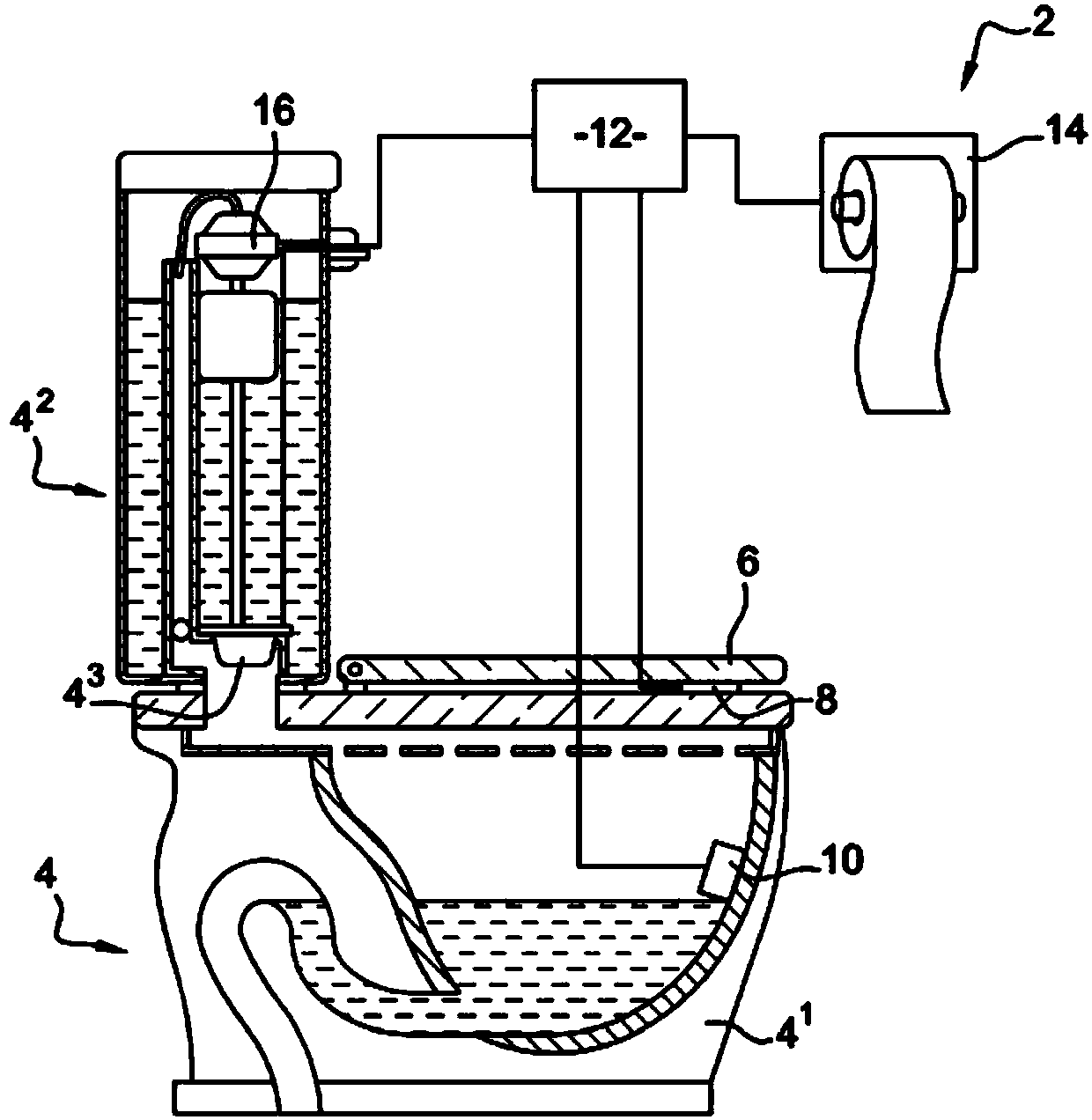
[0031] figure 1 A toilet is shown, more generally denoting a toilet, equipped with a monitoring system according to the invention. The toilet 4 is conventional in that it includes the basin 4 1 and flusher 4 2 , the flusher consists of a tank and serves to direct the water towards the basin 4 1 Discharge valve 4 3 composition. The toilet 4 also includes a toilet seat 6 on the toilet in a conventional manner.

[0032] The system 2 for monitoring the flusher of a toilet 4 comprises means for detecting the presence of a user on the toilet, in this case one or more pressure sensors 8 located under the seat 6, more precisely , in the seat 6 and the basin 4 of the toilet 4 1 between the bearing surfaces on the raceway. The monitoring system 2 also includes a valve 4 for said flusher 3 The electric actuator 16. The pressure sensor 8 and the electric actuator 16 are electrically connected to the monitoring unit 12 . The monitoring system 2 may also comprise a dispenser of t...


PUM


Abstract

The invention concerns a method for controlling a flushing system of a toilet, comprising a step (22) of detecting the consumption of toilet paper and a step (26) of triggering the flushing system depending on the consumption of toilet paper. The method also comprises a step (20) of detecting the presence of the user on the toilet seat, the step (26) of triggering the flushing system depending onthe consumption of toilet paper being conditioned by the detection (20) of the presence of the user on the toilet seat. The invention also concerns a device for controlling a flushing system of a toilet, the device being configured to carry out the abovementioned method.

Description

technical field [0001] The present invention relates to the field of toilets, which are more commonly indicated as "toilets" or "WCs". More specifically, the present invention relates to monitoring toilet flushers. Background technique [0002] Published patent document WO 2010 / 108295 A2 discloses a method and system for controlling a flusher of a toilet. This system essentially comprises a monitoring unit connected to the actuator of the flusher, a dispenser of toilet paper with means for detecting the consumption of said toilet paper, also connected to the monitoring unit. The system also includes fans and alarms connected to a monitoring unit. The monitoring unit is configured to command the flusher as a function of toilet paper consumption. Triggering of the flusher occurs with a time offset of 20 seconds after paper consumption is detected. The amount of water expelled when the flusher is triggered can be proportional to the amount of paper consumed. The fan can al...

Claims


Application Information

Patent Timeline
Patent Type & Authority Applications(China)
IPC IPC(8): E03D5/10
CPCE03D5/105
Inventor 弗兰克.法伯
Owner 弗兰克法伯
Why Eureka
Try Eureka