Method for controlling an impeller-type thread laying device, impeller-type thread laying device, and winding machine
A control device, yarn technology, applied in the field of winder
- Summary
- Abstract
- Description
- Claims
- Application Information
AI Technical Summary
Problems solved by technology
Method used
Image
Examples
Embodiment Construction
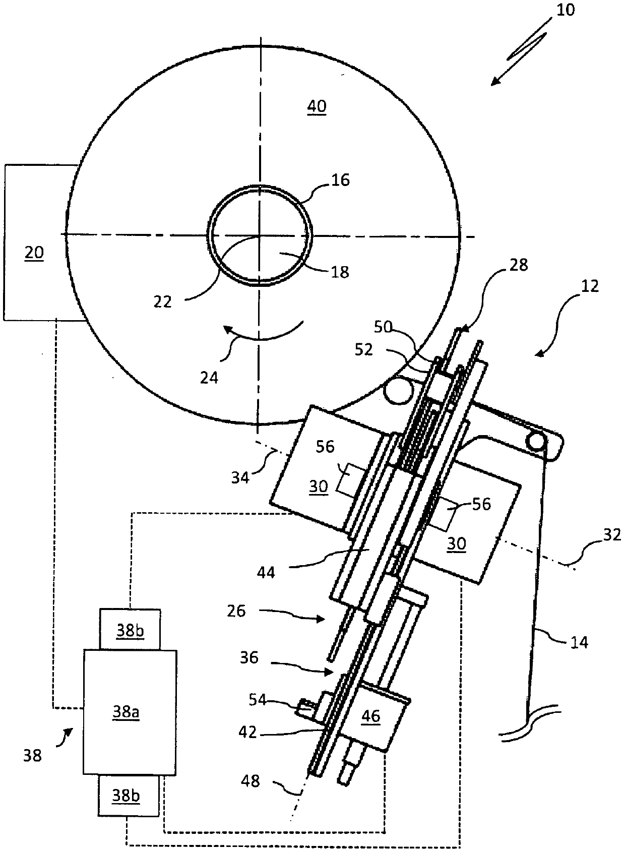
[0040] figure 1 The winding position of a winder 10 with a yarn laying device 12 for winding a yarn 14 onto a bobbin 16 is shown. can be for example in figure 1 The yarn 14 to be wound on a bobbin 16 is provided on a storage bobbin not shown in detail. The bobbin 16 is arranged on a bobbin holder 18 and can be driven in rotation about its longitudinal axis 22 in the direction of the arrow 24 by a bobbin drive 20 .
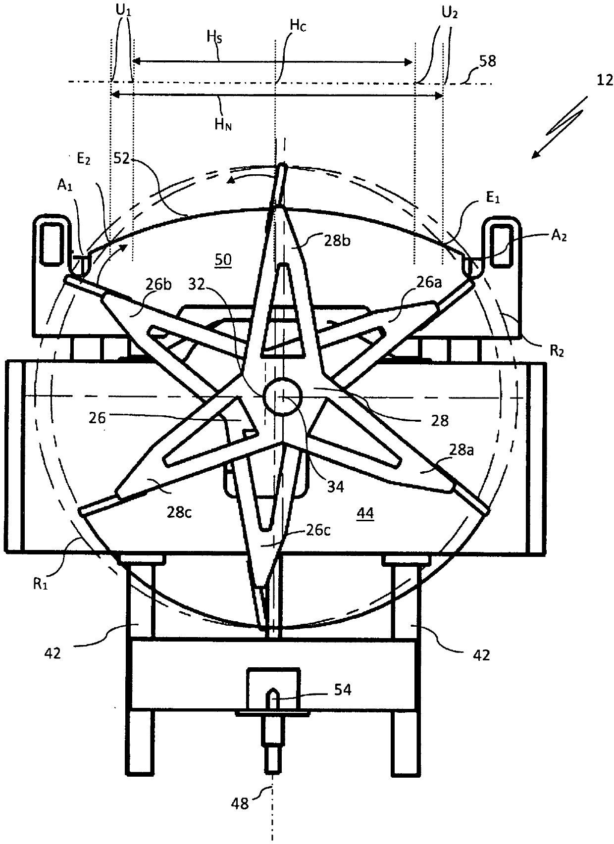
[0041] The thread laying device 12 is designed as a so-called paddle wheel yarn laying device and has two paddle wheels 26 , 28 each. Independently of each other, the two impellers 26 , 28 can be driven in opposite directions about their respective axes of rotation 32 , 34 by means of an electric motor 30 . The electric motor 30 and the impellers 26 , 28 are arranged on a support frame 36 . A control device 38 serves to control the electric motor 30 of the two impellers 26 , 28 and the electric motor 20 of the bobbin holder 18 . The control device 38 has a signa...
PUM
 Abstract
Description
Claims
Application Information
 - R&D
- Intellectual Property
- Life Sciences
- Materials
- Tech Scout
- Unparalleled Data Quality
- Higher Quality Content
- 60% Fewer Hallucinations
Browse by: Latest US Patents, China's latest patents, Technical Efficacy Thesaurus, Application Domain, Technology Topic, Popular Technical Reports.
© 2025 PatSnap. All rights reserved.Legal|Privacy policy|Modern Slavery Act Transparency Statement|Sitemap|About US| Contact US: help@patsnap.com


