
Method for adjusting the brake pedal counterforce in a hydraulic braking system

A brake system and brake pedal technology, applied in the direction of brakes, etc., can solve problems such as the decrease of the reaction force of the hydraulic pressure pedal

Active Publication Date: 2018-03-27
ROBERT BOSCH GMBH
View PDF4 Cites 0 Cited by
  • Summary
  • Abstract
  • Description
  • Claims
  • Application Information

AI Technical Summary

Problems solved by technology

If the driver simultaneously actuates the brake pedal with only a small pedal speed, there is the danger that the hydraulic pressure in the master brake cylinder and thus the pedal reaction force also drops

Method used


Image

  • Method for adjusting the brake pedal counterforce in a hydraulic braking system
  • Method for adjusting the brake pedal counterforce in a hydraulic braking system
  • Method for adjusting the brake pedal counterforce in a hydraulic braking system

Examples


Embodiment Construction

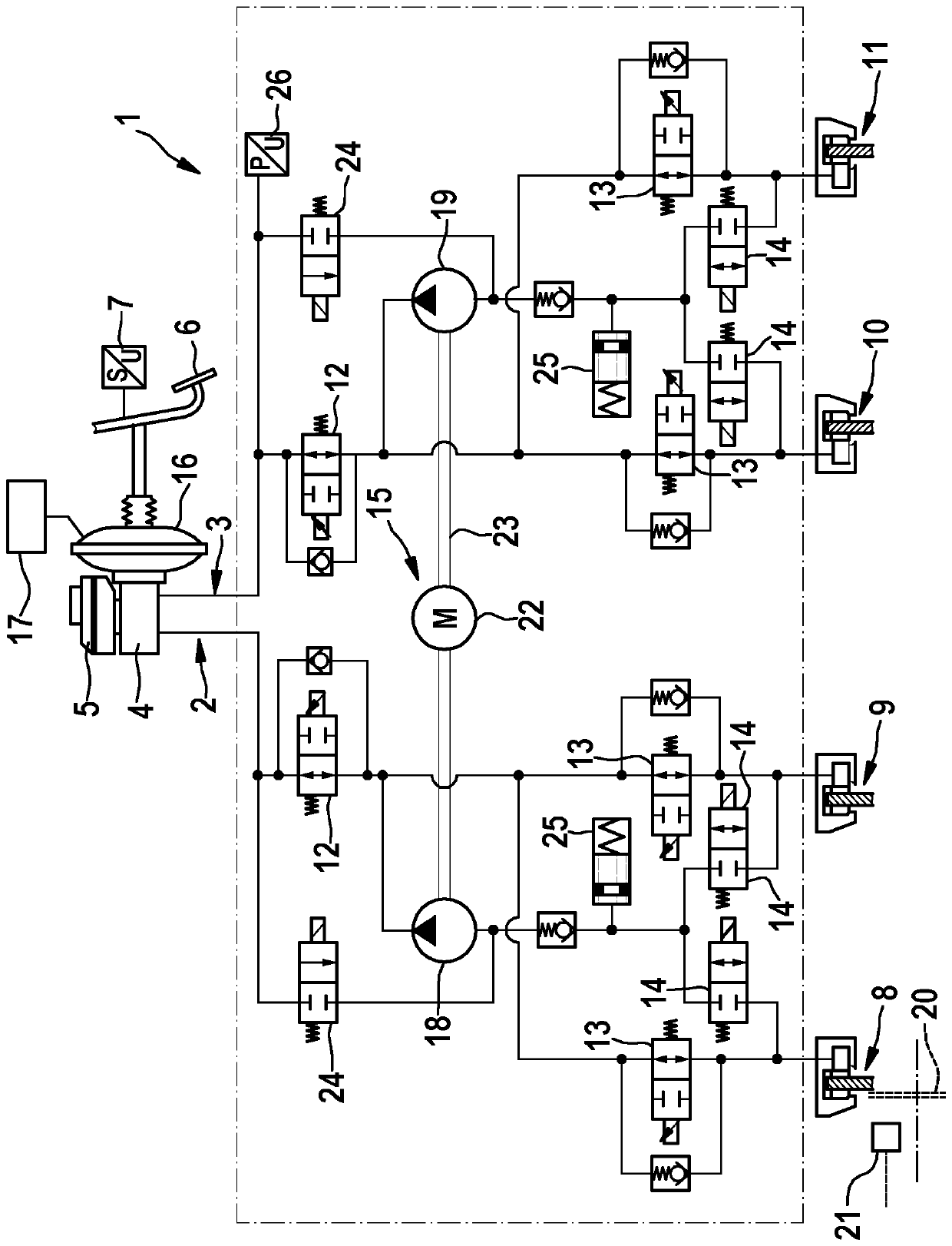
[0020] in accordance with figure 1 The hydraulic brake system 1 shown in the hydraulic circuit diagram has a front axle-brake circuit 2 and a rear axle-brake circuit 3 for forward The wheel brake units 8 and 9 on the wheels or the wheel brake units 10 or 11 on the rear wheels are supplied with hydraulic brake fluid. In principle, brake systems are also conceivable in which the distribution of the brake circuits is diagonal, so that each brake circuit is provided with a wheel brake unit on a front wheel and a rear wheel.

[0021] The two brake circuits 2 , 3 are connected to a common master brake cylinder 4 , and brake fluid is supplied to the master brake cylinder through a brake fluid storage container 5 . Master brake cylinder 4 is actuated by the driver via brake pedal 6 , the pedal travel applied by the driver being measured via pedal travel sensor 7 . A brake booster 16 is located between the brake pedal 6 and the master brake cylinder 4, and the brake booster includes,...


PUM


Abstract

In a method for adjusting the brake pedal counterforce in a hydraulic braking system, a hydraulic pump (18, 19) is controlled in such a way that the hydraulic pressure in the master cylinder (4) doesnot drop below a minimum pressure (pHZ,min) when the brake pedal is actuated.

Description

technical field [0001] The invention relates to a method for adjusting a brake pedal reaction force in a hydraulic brake system. Background technique [0002] A hydraulic brake system in a vehicle is known from DE 10 2009 046 339 A1, which has two brake circuits for supplying hydraulic brake fluid to wheel brake units. The brake circuits are connected to a common master brake cylinder, from which brake fluid is fed into the brake circuit when the brake pedal is actuated. [0003] In each brake circuit is a hydraulic pump which is a component of the anti-lock braking system or of the electronic stability program, via which automatic intervention in the braking system can be carried out. When the hydraulic pump is activated, brake fluid is delivered from the master brake cylinder into the brake circuit. If the driver simultaneously actuates the brake pedal with only a small pedal speed, there is the risk that the hydraulic pressure in the master brake cylinder and thus the p...

Claims


Application Information

Patent Timeline
Patent Type & Authority Applications(China)
IPC IPC(8): B60T8/44B60T8/48
CPCB60T8/442B60T8/4872
Inventor H.福勒特R.沙巴克B.托基克
Owner ROBERT BOSCH GMBH
Learn More