V-shaped horizontal type injection molding machine

An injection molding machine, horizontal technology, applied in the field of V-type horizontal injection molding machine, can solve the problems of poor injection accuracy and stability, large space occupied by the injection mechanism, complicated structure of the injection mechanism, etc., to achieve stable control, simple structure, and reduced occupation. effect of space

Pending Publication Date: 2018-03-27
江门市汇力精密机械有限公司
View PDF9 Cites 2 Cited by
  • Summary
  • Abstract
  • Description
  • Claims
  • Application Information

AI Technical Summary

Problems solved by technology

[0002] In the prior art, the injection molding machine usually includes an injection mechanism and a mold forming mechanism. The injection mechanism includes a feed cylinder and an injection cylinder, but the injection cylinder of the existing injection molding machine is generally arranged horizontally, and the supply cylinder is vertically injected into the cylinder. If it is installed, the injection mechanism will take up a lot of space, and the feeding cylinder cannot be set too long, otherwise it will lead to poor structural rigidity, and the injection screw is also a plasticizing cylinder, which is prone to reverse flow of plastic raw materials during injection. Phenomenon, so a non-return ring must be provided at the end of the connection between the supply cylinder and the injection cylinder, which makes the structure of the injection mechanism complex, and the injection accuracy and stability are poor

Method used


Image

  • V-shaped horizontal type injection molding machine
  • V-shaped horizontal type injection molding machine

Examples


Embodiment Construction

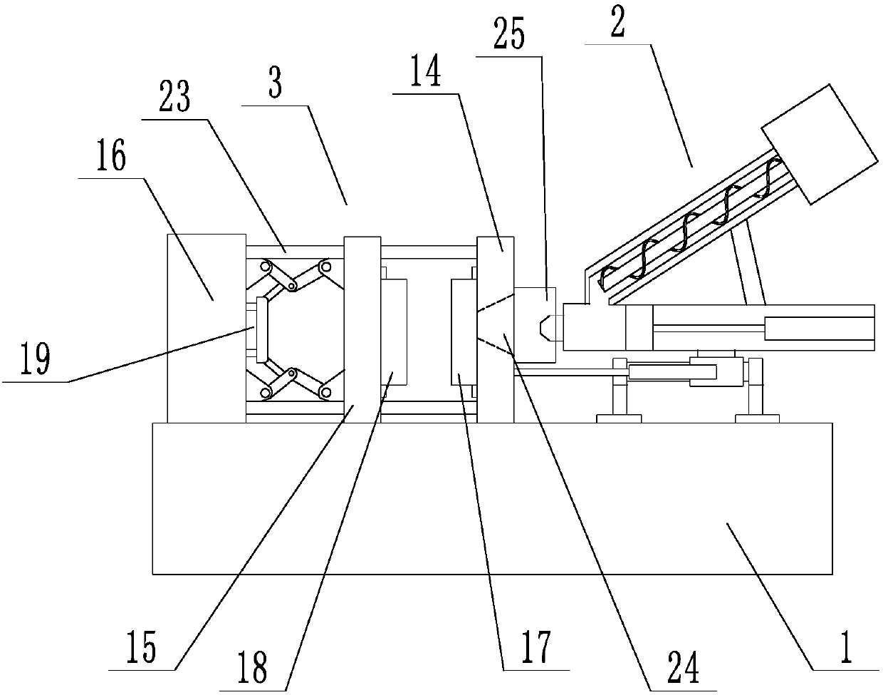
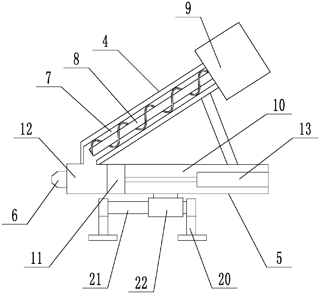
[0017] Such as figure 1 and figure 2 As shown, a V-shaped horizontal injection molding machine includes a base 1 on which an injection unit 2 and a mold forming unit 3 are arranged. The injection unit 2 includes a supply cylinder 4, an injection cylinder 5 and an injection nozzle 6. The injection cylinder 5 is set horizontally, and the supply cylinder 4 is set upwardly. The bottom end of the supply cylinder 4 is connected with one end of the injection cylinder 5 to form a V-shaped structure. The top of the supply cylinder 4 is connected to the injection material through a support column. The other end of the barrel 5 is connected, so that the structural strength between the feeding barrel 4 and the injection barrel 5 can be improved. The feeding barrel 4 is provided with a feeding channel 7, and the feeding channel 7 is provided with a heating device and a conveying screw 8. And the first driving device 9 that drives the delivery screw 8 to rotate, the injection barrel 5 is ...


PUM


Abstract

The invention discloses a V-shaped horizontal type injection molding machine. The V-shaped horizontal type injection molding machine comprises a base. The base is provided with an injection unit and amold molding unit. The injection unit comprises a material supply barrel, an injection material barrel and an injection nozzle. The injection material barrel is horizontally arranged, and the material supply barrel is arranged upwards in an inclined manner. The material supply barrel is internally provided with a material supply channel. The material supply channel is internally provided with a heating device, a conveying threaded rod and a first driving device, wherein the conveying threaded rod is driven by the first driving device. The injection barrel is internally provided with an injection channel. The injection channel is internally provided with a plunger. An injection cavity is formed in the connection position of the material supply barrel and the injection material barrel, wherein the injection cavity enables the material supply channel to communicate with the injection channel. The injection nozzle communicates with the injection cavity. The injection material barrel is connected with the base in a sliding manner. The mold molding unit comprises a fixed mold plate, a movable mold plate, a support plate, a fixed mold and a movable mold, wherein the fixed mold plate, themovable mold plate and the support plate are sequentially arranged. The V-shaped horizontal type injection molding machine has the beneficial effects of being simple in structure, high in structuralstrength, precise in injection metering control, stable in injection and the like.

Description

technical field [0001] The invention relates to an injection molding machine, in particular to a V-shaped horizontal injection molding machine. Background technique [0002] In the prior art, the injection molding machine usually includes an injection mechanism and a mold forming mechanism. The injection mechanism includes a feed cylinder and an injection cylinder, but the injection cylinder of the existing injection molding machine is generally arranged horizontally, and the supply cylinder is vertically injected into the cylinder. If it is installed, the injection mechanism will take up a lot of space, and the feeding cylinder cannot be set too long, otherwise it will lead to poor structural rigidity, and the injection screw is also a plasticizing cylinder, which is prone to reverse flow of plastic raw materials during injection. Phenomenon, so a non-return ring must be provided at the end of the connection between the supply cylinder and the injection cylinder, which make...

Claims


Application Information

Patent Timeline
Patent Type & Authority Applications(China)
IPC IPC(8): B29C45/54B29C45/03
CPCB29C45/03B29C45/54
Inventor 胡景江
Owner 江门市汇力精密机械有限公司
Why Eureka
Try Eureka