Screw-type injection molding machine discharging device structure

A device structure and injection molding machine technology, applied in the field of screw-type injection molding machine blanking device structure, can solve the problems of inability to clean materials, inability to adjust the position of the screw, and affecting operation and use.

Inactive Publication Date: 2018-03-27
郭文英
View PDF3 Cites 2 Cited by
  • Summary
  • Abstract
  • Description
  • Claims
  • Application Information

AI Technical Summary

Problems solved by technology

However, this device cannot clean up the materials accumulated on the inner wall of the falling hopper, and cannot adjust the position of the screw, which affects the operation and use.

Method used


Image

  • Screw-type injection molding machine discharging device structure
  • Screw-type injection molding machine discharging device structure
  • Screw-type injection molding machine discharging device structure

Examples


Embodiment Construction

[0022] The following will clearly and completely describe the technical solutions in the embodiments of the present invention with reference to the accompanying drawings in the embodiments of the present invention. Obviously, the described embodiments are only some, not all, embodiments of the present invention.

[0023] Example.

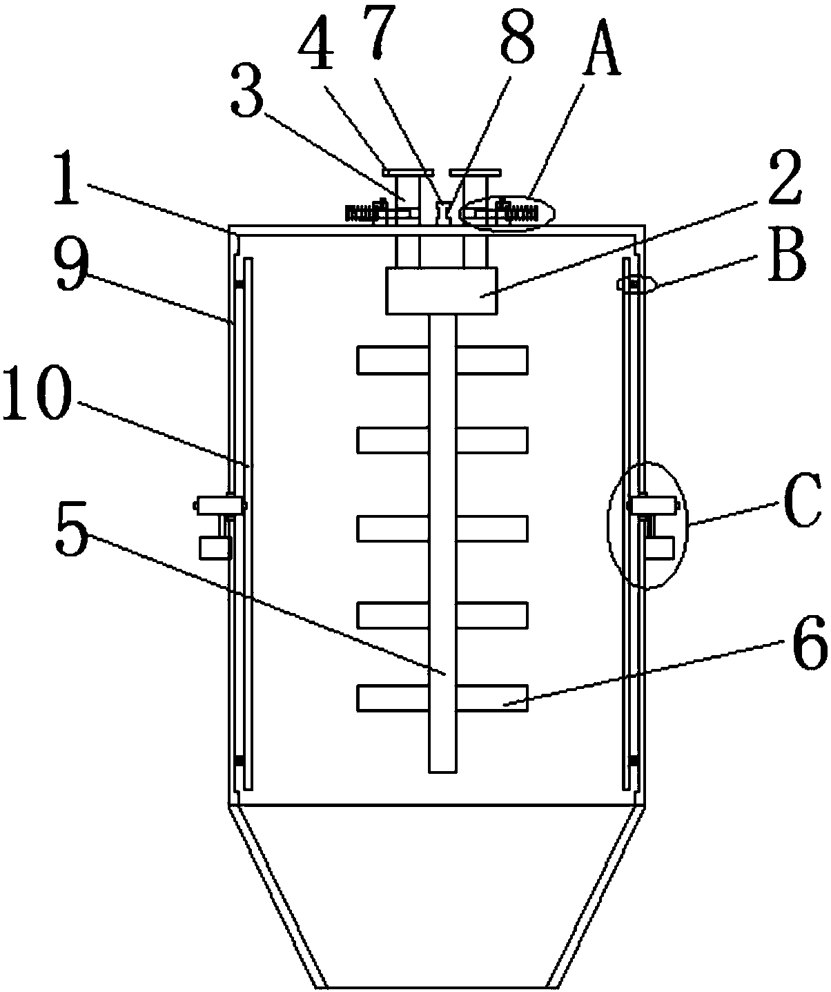
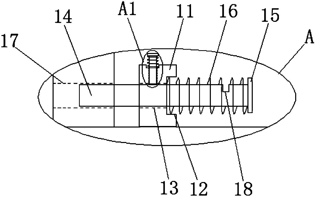
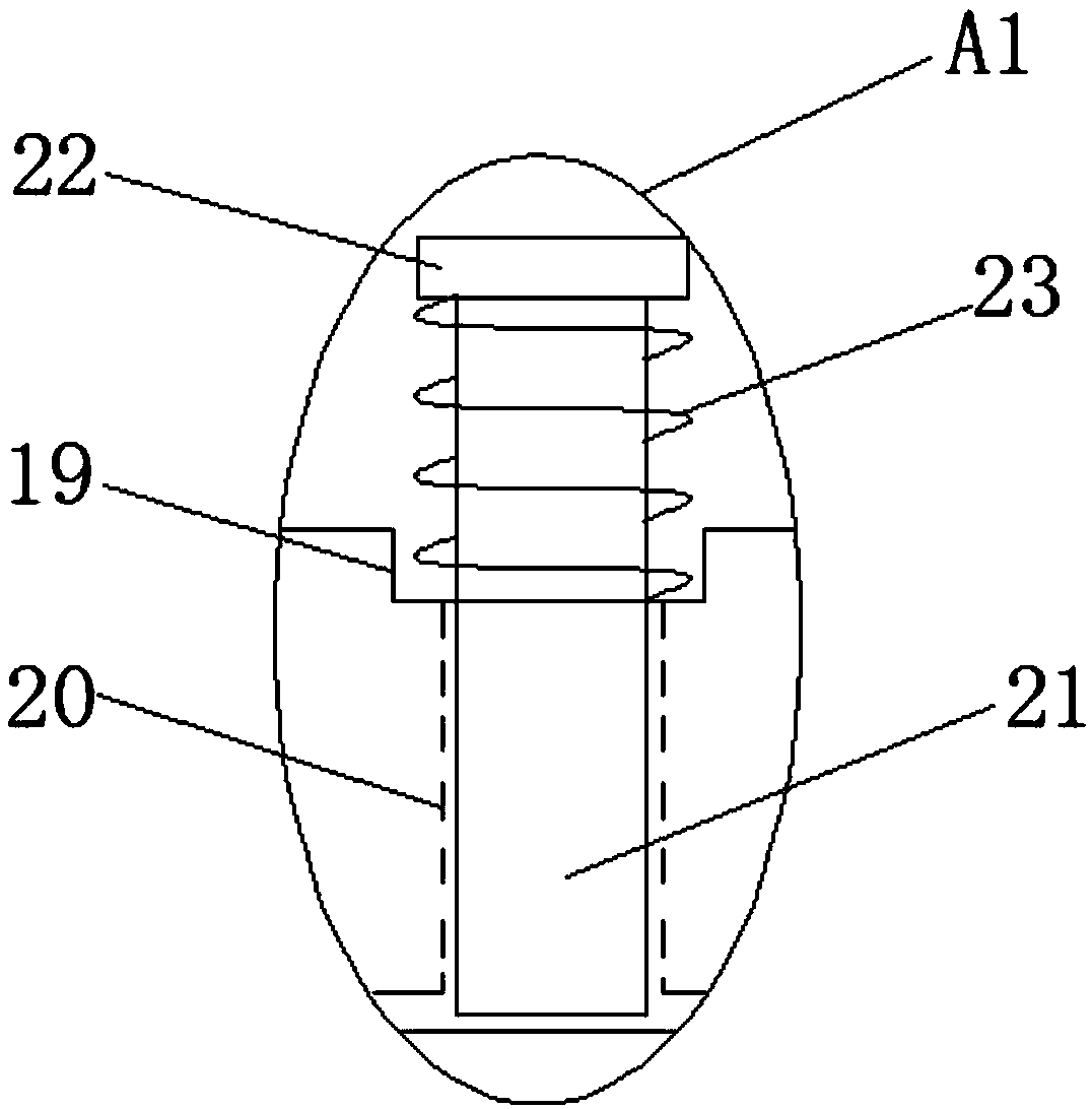
[0024] refer to Figure 1-5, a screw-type injection molding machine blanking device structure, including a blanking funnel 1, the inside of the blanking funnel 1 is movable installed with a rotating motor 2, the output shaft of the rotating motor 2 is fixedly installed with a rotating shaft 5, and both sides of the rotating shaft 5 are A plurality of stirring blades 6 are fixedly installed, and two connecting rods 3 are fixedly installed on the top side of the rotating motor 2, and the tops of the two connecting rods 3 both extend to the top of the feeding funnel 1, and both of them are fixedly installed with a limit block 4 There is a first fixed ...


PUM


Abstract

The invention discloses a screw-type injection molding machine discharging device structure which comprises a discharging funnel. A rotating motor is movably installed inside the discharging funnel. An output shaft of the rotating motor is fixedly provided with a rotating shaft. A plurality of stirring blades are both fixedly installed at the two sides of the rotating shaft. Two connecting rods are fixedly installed at the top side of the rotating motor, and the top ends of the two connecting rods both extend to the position above the discharging funnel and are both fixedly provided with limiting blocks. A first fixing block which is fixedly installed at the top of the discharging funnel is arranged between the two connecting rods. The sides, keeping away from each other, of the two connecting rods are both provided with second fixing blocks which are fixedly installed at the top of the discharging funnel. The sides, keeping away from each other, of the two second fixing blocks are both provided with mounting grooves. According to the screw-type injection molding machine discharging device structure, the positions of the rotating shaft and the stirring blades inside the dischargingfunnel can be adjusted stably and conveniently, and stirring can be conducted at various height positions conveniently. Meanwhile, a moving plate can vibrate in the discharging funnel conveniently, and dropping of materials accumulated on the inner wall of the discharging funnel can be facilitated.

Description

technical field [0001] The invention relates to the technical field of an injection molding machine unloading device, in particular to a structure of a screw type injection molding machine unloading device. Background technique [0002] The existing blanking device of injection molding machine generally has a simple structure, and bridging phenomenon is easy to occur during the blanking process. In order to avoid the bridging phenomenon, the structure needs to be improved reasonably. [0003] The patent application number is 201310433140.3 discloses a screw type injection molding machine blanking device structure,: said screw type injection molding machine blanking device structure, including injection molding machine blanking hopper, power output device, coupling, screw; wherein: A power take-off device is installed on the top of the injection molding machine drop hopper, and the screw is connected with the power take-off device through a coupling. The power output device ...

Claims


Application Information

Patent Timeline
IPC IPC(8): B29C45/18
CPCB29C45/18
Inventor 郭文英
Owner 郭文英
Why Eureka
Try Eureka