
Imaging lens and laser thickness measurement device employing same

An imaging lens and laser thickness measurement technology, applied in the direction of using optical devices, measuring devices, optics, etc., can solve the problems of small measurement range and low measurement accuracy of rangefinders, and achieve small lens length, high measurement accuracy, and accurate calibration. poor effect

Inactive Publication Date: 2018-03-23
SUZHOU PTC OPTICAL INSTR
View PDF1 Cites 4 Cited by
  • Summary
  • Abstract
  • Description
  • Claims
  • Application Information

AI Technical Summary

Problems solved by technology

However, limited by the resolution and measurement range of the imaging lens group, the rangefinder has a small measurement range and low measurement accuracy.

Method used


Image

  • Imaging lens and laser thickness measurement device employing same
  • Imaging lens and laser thickness measurement device employing same
  • Imaging lens and laser thickness measurement device employing same

Examples


Embodiment 1

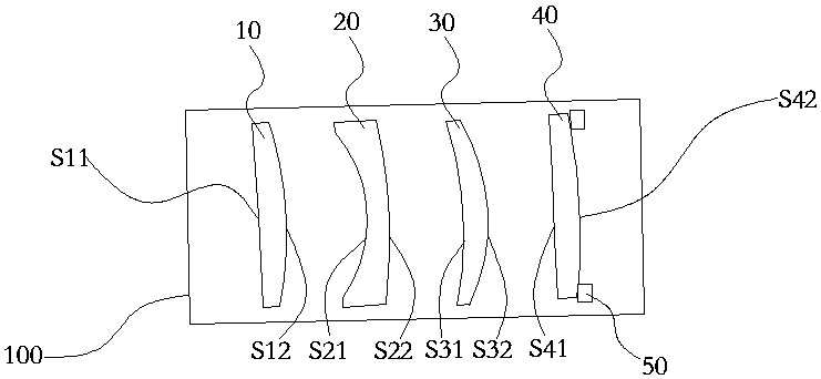
[0032] figure 1 A schematic structural diagram of an embodiment of the imaging lens of the present invention is shown, which is also a schematic diagram of a preferred embodiment. Such as figure 1 As shown, the imaging lens 100 described in this embodiment sequentially includes from the object side to the image side along the optical axis: a first lens 10 with positive refractive power, the first lens has a first object facing the object side Side S11, a first image side S12 facing the image side; a second lens 20 with negative refractive power, the second lens 20 has a second object side S21 facing the object side, facing the image side The second image side S22 of the; has the third lens 30 of positive refractive power, and the third lens 30 has the third object side S31 toward the object side, the third image side S22 toward the image side; and has The fourth lens 40 with positive refractive power, the fourth lens 40 has a fourth object side S41 facing the object side, an...

Embodiment 2

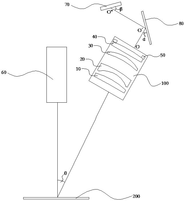
[0036] This embodiment provides a laser thickness measuring device using the imaging lens 100 described in Embodiment 1, such as figure 2 As shown, the laser thickness measuring device described in this embodiment includes: a laser 60, the imaging lens 100 described in Embodiment 1, and a photodetector 70. The laser beam emitted by the laser 60 passes through the object to be measured 200, the imaging The first lens 10 , the second lens 20 , the third lens 30 and the fourth lens 40 of the lens 100 converge on the photodetector 70 afterward.

[0037] As a preferred implementation mode, the imaging size X of the photodetector 70 in this embodiment is:

[0038]

[0039]Wherein, Y and L are respectively the maximum and minimum distances between the laser 60 and the object to be measured 200, L-Y is the thickness of the object to be measured, f is the focal length of the imaging system, and l is the distance from the laser to the center of the imaging lens.

[0040] As a prefe...


PUM


Abstract

The invention belongs to the field of optical elements and optical detection, and especially relates to an imaging lens and a laser thickness measurement device employing the same. The imaging lens sequentially comprises a first lens with the positive focal power, a second lens with the negative focal power, a third lens with the positive focal power and a fourth lens with the positive focal poweralong the optical axis from the object space to the image space, and meets conditional expressions: 0.5<F2 / F<1 and R4>R5>R6. Therefore, the imaging lens can effectively shorten the total length, canavoid the severe spherical aberration, can correct coma, is good in imaging quality, is small in length, facilitates the installation and debugging, is large in measurement range, is high in measurement speed, is high in measurement precision, and is good in application prospect.

Description

technical field [0001] The invention belongs to the field of optical elements and optical detection, in particular to an imaging lens and a laser thickness measuring device using the imaging lens. Background technique [0002] As we all know, an imaging lens is an optical imaging device composed of a lens group. In order to improve the imaging quality, the imaging lens usually includes a plurality of lenses, for example, an imaging lens including four lenses includes a first lens and a second lens from the object side to the image side. Usually, due to cost and manufacturability considerations, both the first lens and the second mirror use aspheric plastic lenses, but the types of optical plastics used to produce plastic lenses are very limited, and the range of optical parameters of the refractive index and Abbe coefficient is small. High dispersion and limited ability to correct for chromatic aberrations result in poor image quality. However, if both the first lens and t...

Claims


Application Information

Patent Timeline
Patent Type & Authority Applications(China)
IPC IPC(8): G02B13/00G02B1/00G01B11/06
CPCG02B13/0015G01B11/06G02B1/00
Inventor 刘柱
Owner SUZHOU PTC OPTICAL INSTR
Learn More