Finite element analysis method of electromagnetic fields near direct-current grounding electrode and tower grounding grid

A technology of DC grounding and analysis method, applied in the fields of electromagnetic field characteristics, measurement of electrical variables, measurement devices, etc., can solve problems such as incomplete finite element analysis

Active Publication Date: 2018-03-23
XIAN UNIV OF TECH
View PDF11 Cites 7 Cited by
  • Summary
  • Abstract
  • Description
  • Claims
  • Application Information

AI Technical Summary

Problems solved by technology

[0005] The purpose of the present invention is to provide a finite element analysis method of the electromagnetic field near the DC grounding pole and the tower grounding grid, which solves the problem that the finite element analysis of the electromagnetic field near the DC grounding pole and the tower grounding grid is not comprehensive in the prior art

Method used


Image

  • Finite element analysis method of electromagnetic fields near direct-current grounding electrode and tower grounding grid
  • Finite element analysis method of electromagnetic fields near direct-current grounding electrode and tower grounding grid
  • Finite element analysis method of electromagnetic fields near direct-current grounding electrode and tower grounding grid

Examples


Embodiment Construction

[0056] The present invention will be described in detail below in conjunction with the accompanying drawings and specific embodiments.

[0057] The finite element analysis method of the electromagnetic field near the DC grounding pole and the tower grounding grid of the present invention is specifically implemented according to the following steps:

[0058] Step 1. Build a model and set relevant parameters, specifically:

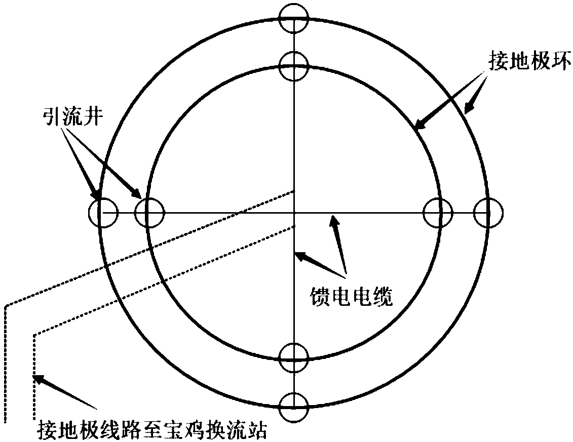
[0059] For the DC grounding electrode: establish the DC grounding electrode model, set the radius R of the inner and outer rings of the circular grounding electrode 1 and R 2 , the cross-sectional diameter D of a single polar ring 1 , the buried depth of the ground electrode is h 1 , a layer of carbon layer is covered around the ground electrode ring, and the size of the outer ring carbon layer is m 1 *m 1 , the carbon layer size of the inner ring is m 2 *m 2 ;

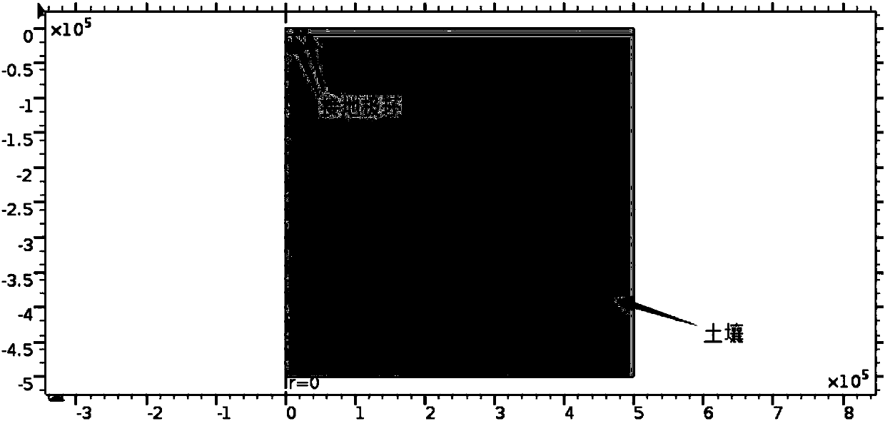
[0060] Let the soil model be a four-layer soil model, and the layer depths are H 1 = 0-...


PUM


Abstract

The invention discloses a finite element analysis method of electromagnetic fields near a direct-current grounding electrode and a tower grounding grid. Model establishment, relevant parameter setting, material attribute adding, boundary condition adding, grid division, and electromagnetic field distribution calculation are carried out to obtain the following conclusions: potentials of two groundpolar rings are the highest and the voltage of the inner ring is slightly higher than that of the outer ring, the potentials are reduced gradually along the radial direction by using the circle centerof the ground polar ring as the starting point, and the potential of the soil of the inner ring is higher than that of the soil of the outer ring; and the potential of a tower grounding grid body isthe highest, the potential of the tower grounding rid is increased gradually when the distance to the tower grounding rid is reduced, the potential of the soil inside the tower grounding rid is higherthan that of the soil outside the tower grounding rid, the potential near the tower grounding rid is symmetric because of the symmetry of the tower grounding rid, the leakage current density at the tail end of a ray of the grounding grid is the largest and the current density at the front end of the ray is the lowest, and the current density at the connection part between the rectangle and the ray of the grounding grid changes suddenly. Therefore, a problem of an incomprehensive finite element analysis of electromagnetic fields near a direct-current grounding electrode and a tower grounding grid is solved.

Description

technical field [0001] The invention belongs to the technical field of electric power systems and automation thereof, and in particular relates to a finite element analysis method for electromagnetic fields near DC grounding poles and tower grounding grids. Background technique [0002] When the DC transmission system is in the operation mode of single-pole ground return line, a large DC current will flow into the ground through the DC grounding electrode, which will cause corrosion of the grounding electrode itself and the grounding grid of nearby transmission towers. Therefore, it is of great significance to study the distribution of the electric field around the DC grounding electrode and the distribution of the electric field and leakage current density around the leakage current flowing into the grounding grid of the tower. [0003] The existing literature has some research on the electromagnetic field calculation of the DC grounding pole and the nearby tower grounding ...

Claims


Application Information

Patent Timeline
Patent Type & Authority Applications(China)
IPC IPC(8): G01R29/08
CPCG01R29/0892
Inventor 杨晓萍郭扬
Owner XIAN UNIV OF TECH
Why Eureka
Try Eureka