
Double lock type door and window handle assembly

A component and handle technology, which is applied in the field of anti-lock door and window handle components, can solve the problems of inconsistency, inconvenience in use, asymmetric appearance inside and outside, and achieve the effect of reasonable overall structure

Active Publication Date: 2018-03-23
徐志克
View PDF5 Cites 3 Cited by
  • Summary
  • Abstract
  • Description
  • Claims
  • Application Information

AI Technical Summary

Problems solved by technology

[0002] At present, most of the door locks on the market have a double lock core structure. The door handle and the outside handle can control the lock bolt through the corresponding lock core to achieve the purpose of opening or locking the door. However, due to the use requirements of indoor doors, especially It is the door of the bathroom. The inward side of the door lock used in these occasions is usually equipped with a locking device. The door lock is completely locked from the inside of the door, and the door lock is opened from the outside. The locking device is usually controlled by a knob, which is set on the The door lock inside the door is separate from the door handle to control the lock cylinder. The knob makes the overall appearance asymmetrical inside and outside, and it is not simple, and it needs to be unlocked through the knob, and then unlocked through the door handle, which is inconvenient to use

Method used


Image

  • Double lock type door and window handle assembly
  • Double lock type door and window handle assembly
  • Double lock type door and window handle assembly

Examples


Embodiment Construction

[0027] The present invention will be further described below in conjunction with accompanying drawing and embodiment:

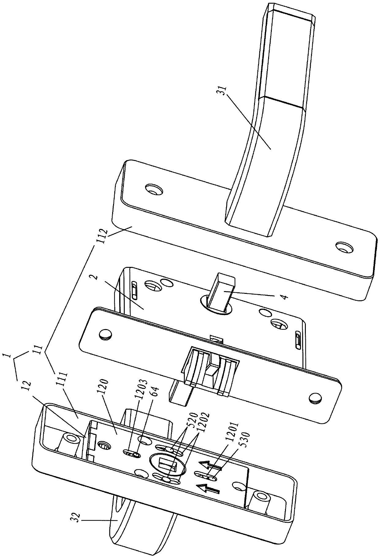
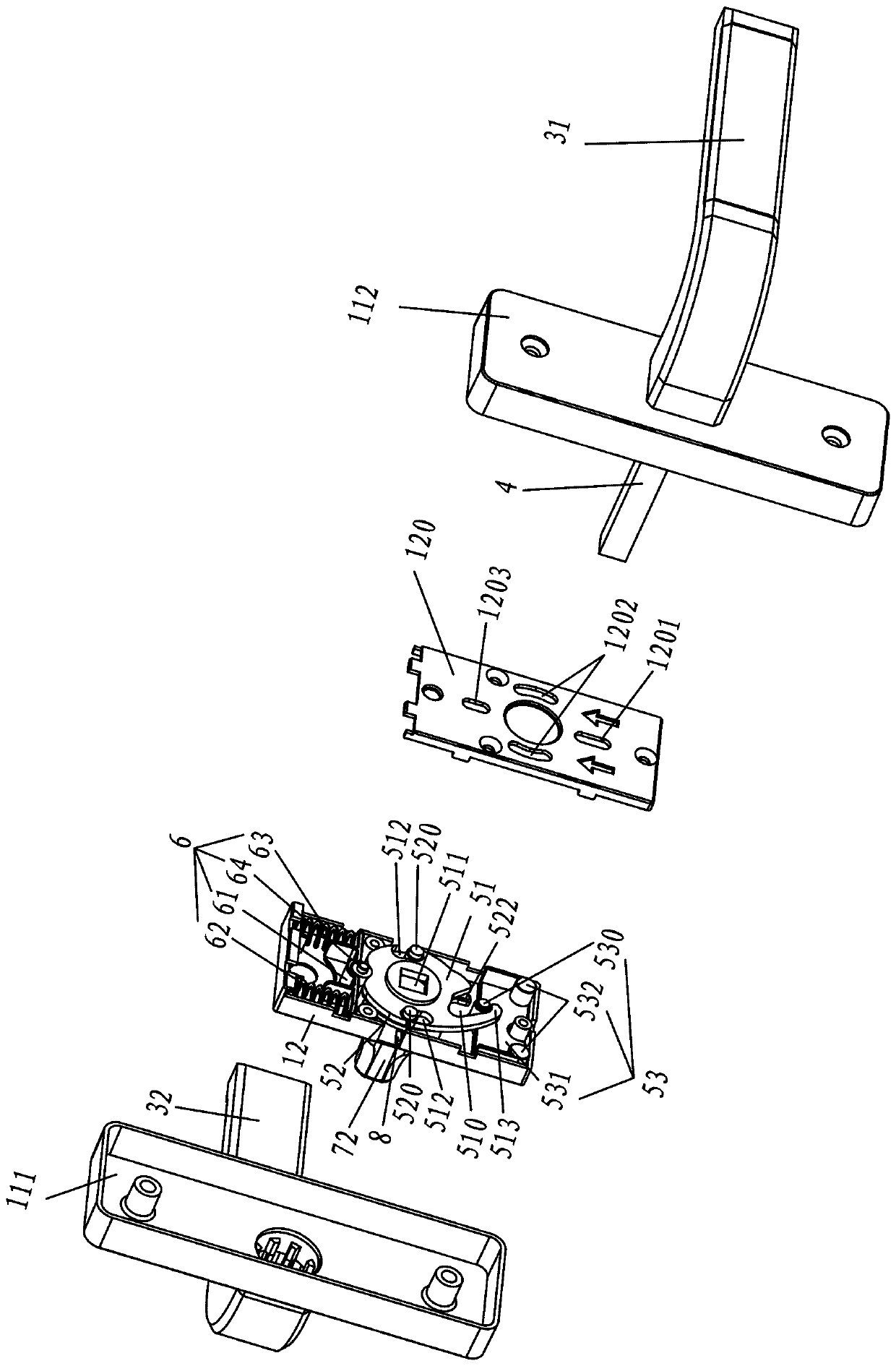
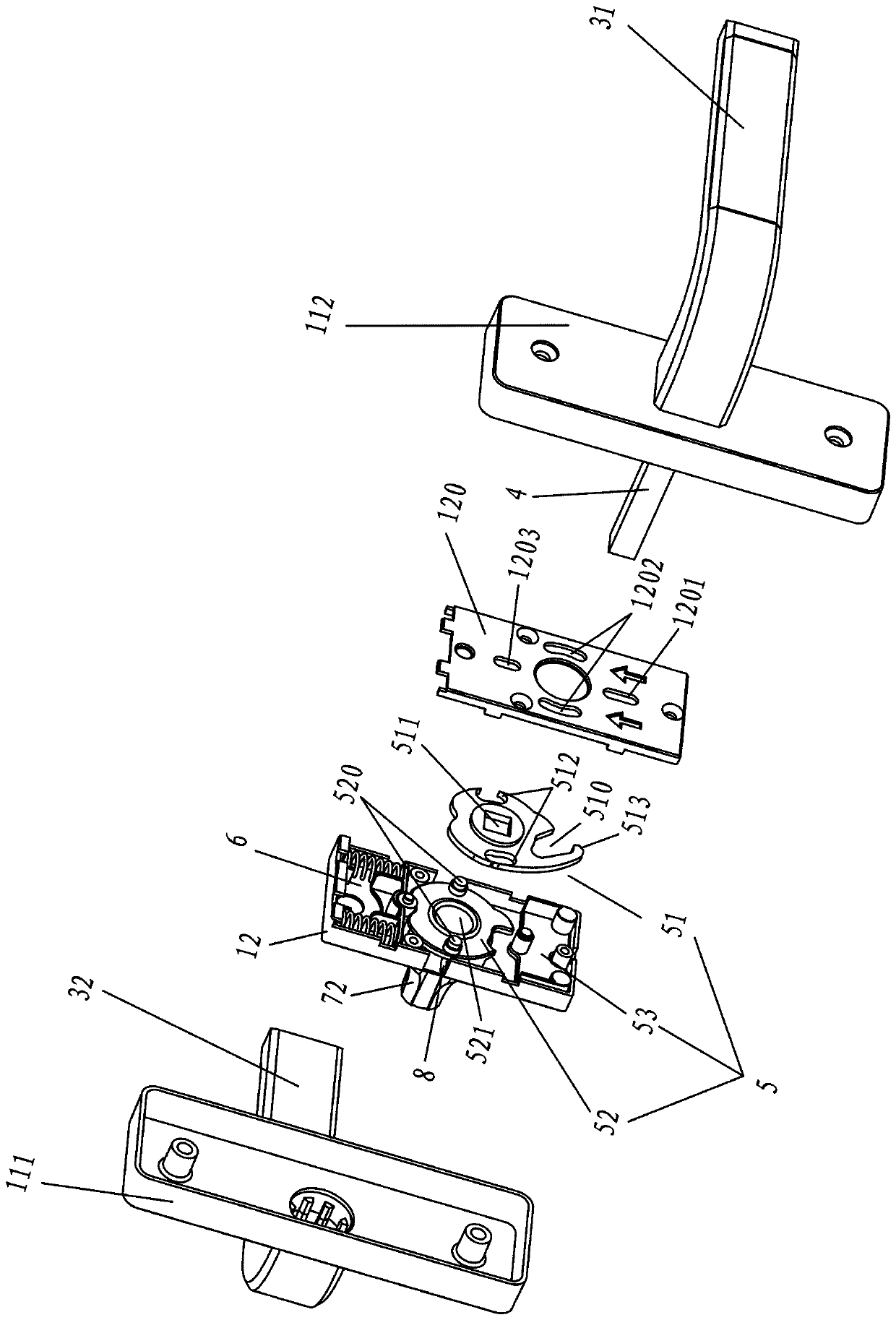
[0028] see Figure 1 to Figure 4 As shown, the anti-locking door and window handle assembly includes a housing 1, and an inner handle 31, a locking bar 4, an anti-locking assembly 5, an outer handle lock cylinder 72 and an outer handle 32 arranged on the housing 1, and the inner handle 31 is connected to the locking bar 4. The outer handle 32 is connected to the outer handle lock cylinder 72, the outer handle lock cylinder 72 is provided with a blocking member 52, the anti-lock assembly 5 includes an anti-lock member 51 and an anti-lock position device 53, and the anti-lock member 51 has an anti-lock hook groove 510, lock bar pushing hole 511 and blocking piece guide hole 512, blocking piece 52 is connected with outer handle lock core 72, and blocking piece 52 is also provided with derivation column 520, and the deriving column 520 of blocking piece 52 is ins...


PUM


Abstract

The invention discloses a double lock type door and window handle assembly which comprises a shell, an inner handle, a lock bar, a double lock assembly, an outer handle lock cylinder and an outer handle. The inner handle is connected with the lock bar. The outer handle is connected with the outer handle lock cylinder. A blocking part is arranged on the outer handle lock cylinder. The double lock assembly comprises a double lock part and a double lock locating device. A double lock hook groove, a lock bar pushing hole and blocking part guide holes are arranged on the double lock part. The blocking part is connected with the outer handle lock cylinder. Push guide columns are arranged on the blocking part and are inserted into the blocking part guide holes. The double lock locating device ismounted on the shell in a manner of being capable of shifting. A limiting column is arranged on the double lock locating device and arranged in the double lock hook groove. The inner handle drives thedouble lock part through the lock bar. The double lock part pushes the limiting column to shift through the double lock hook groove and drives the double lock locating device to shift, so that the limiting column abuts against the blocking part, and movement of the outer handle lock cylinder and the outer handle is limited. According to the double lock type door and window handle assembly, the double lock assembly is not additionally provided with a control switch, only the handles are mounted outside the shell, and the overall structure is reasonable and simple.

Description

technical field [0001] The invention relates to the technical field of door and window handle assemblies, in particular to an anti-locking door and window handle assembly. Background technique [0002] At present, most of the door locks on the market have a double lock core structure. The door handle and the outside handle can control the lock bolt through the corresponding lock core to achieve the purpose of opening or locking the door. However, due to the use requirements of indoor doors, especially It is the door of the bathroom. The inward side of the door lock used in these occasions is usually equipped with a locking device. The door lock is completely locked from the inside of the door, and the door lock is opened from the outside. The locking device is usually controlled by a knob, which is set on the The door lock inside the door is separate from the door handle to control the lock cylinder. The knob makes the overall appearance asymmetrical inside and outside, and ...

Claims


Application Information

Patent Timeline
IPC IPC(8): E05B3/00E05B17/20E05B13/00E05B9/00
CPCE05B3/00E05B9/00E05B13/002E05B17/20
Inventor 徐志克
Owner 徐志克
Learn More