
Three-row weighing and filling machine

A filling machine and weighing technology, applied in the directions of packaging, transportation and packaging, and the type of packaged items, can solve the problems of restricting the filling efficiency of multi-container filling machines, long time for changing containers, and limited number of tube heads. , to achieve the effect of improving filling efficiency, facilitating pushing barrels and filling materials, and reducing replacement time

Pending Publication Date: 2018-03-20
江苏汤姆森智能装备有限公司
View PDF5 Cites 2 Cited by
  • Summary
  • Abstract
  • Description
  • Claims
  • Application Information

AI Technical Summary

Problems solved by technology

However, the current multi-containers are all ring-shaped structures, that is, the containers move around the central filling mechanism. The disadvantages are: ①, the number of pipe heads is limited, that is, the number of containers that are filled each time is limited; ②, each time It takes a long time for the container to be sent out after filling, that is, it takes a long time to replace the container
These two deficiencies restrict the filling efficiency of the multi-container filling machine

Method used


Image

  • Three-row weighing and filling machine
  • Three-row weighing and filling machine
  • Three-row weighing and filling machine

Examples


Embodiment 1

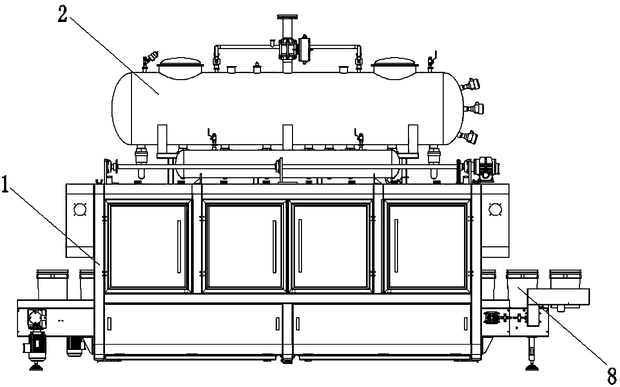
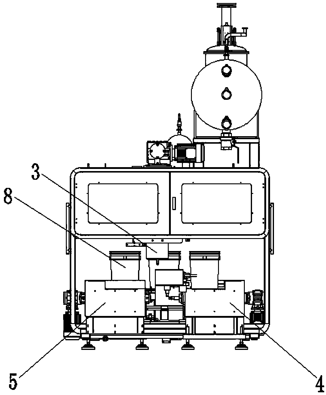
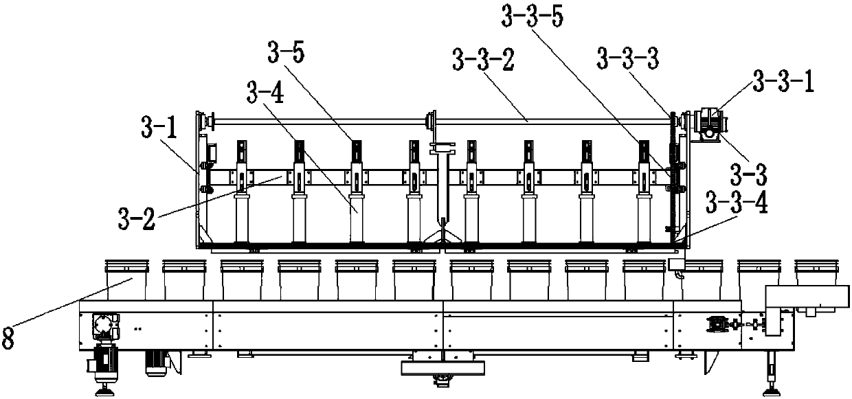
[0043] See Figure 1 to Figure 11 , The three-row weighing filling machine of this embodiment includes a cabinet 1, a material tank 2, a filling mechanism 3, a container feeding mechanism 4, a container sending mechanism 5, a weighing filling platform 6 and a container pushing mechanism 7.

[0044] The material tank 2 is fixed on the top of the cabinet 1 . The filling mechanism 3 is arranged in the cabinet 1 and communicated with the material tank 2 . The container feeding mechanism 4 passes through from one side of the cabinet 1 , and the container sending mechanism 5 passes through from the other side of the cabinet 1 . The weighing filling platform 6 is arranged in the cabinet 1, and is located between the container feeding mechanism 4 and the container sending mechanism 5, and is also located directly below the filling mechanism 3. The container pushing mechanism 7 is arranged in the cabinet 1, and the container pushing mechanism 7 pushes the container 8 to move between ...

Embodiment 2

[0054] This embodiment is basically the same as Embodiment 1, except that the container 8 is a bottle-shaped container. The container pushing mechanism 7 is arranged above the container feeding mechanism 4 . The container pushing mechanism 7 comprises a bottle push support, a bottle push cylinder and a bottle push cross bar. The cylinder body of the bottle pushing cylinder is arranged on the bottle pushing support. Push bottle cylinder. The bottle pushing cylinder drives the bottle pushing cross bar to move between the top of the container feeding mechanism 4 and the top of the weighing filling platform 6 .


PUM


Abstract

The invention discloses a three-row weighing and filling machine comprising a cabinet, a material tank, a material filling mechanism, a container feed-in mechanism, a container send-out mechanism, a weighing and material filling platform and a container push mechanism. The material tank is fixed to the top of the cabinet. The material filling mechanism is arranged in the cabinet and communicates with the material tank. The container feed-in mechanism penetrates in from one side of the cabinet, and the container send-out mechanism penetrates out from the other side of the cabinet. The weighingand material filling platform is arranged in the cabinet, located between the container feed-in mechanism and the container send-out mechanism and located under the material filling mechanism at the same time. The container push mechanism is arranged in the cabinet and pushes containers to move between the container feed-in mechanism, the weighing and material filling platform and the container send-out mechanism. By means of the three-row weighing and filling machine, the number of the containers where material filling is conducted each time can be greatly increased, and meanwhile all the containers are sent out at the same time; and the container replacement time is greatly shortened, and therefore the filling efficiency is greatly improved.

Description

technical field [0001] The invention relates to a three-row weighing filling machine. Background technique [0002] The multi-container filling machine can fill multiple containers at the same time, which effectively improves the filling efficiency. However, the current multi-containers are all ring-shaped structures, that is, the containers move around the central filling mechanism. The disadvantages are: ①, the number of pipe heads is limited, that is, the number of containers that are filled each time is limited; ②, each time After the filling is completed, it takes a long time to send out the container, that is, it takes a long time to replace the container. These two deficiencies restrict the filling efficiency of the multi-container filling machine. Contents of the invention [0003] The purpose of the present invention is to provide a three-row weighing filling machine, which can greatly increase the number of containers to be filled each time, and send out all th...

Claims


Application Information

Patent Timeline
IPC IPC(8): B65B43/48B65B43/52B65B3/28B65B39/12
CPCB65B3/28B65B39/12B65B43/48B65B43/52Y02E60/10
Inventor 汤建华徐根宝刘路夏斌陈传芳陈玉龙
Owner 江苏汤姆森智能装备有限公司
Learn More