


Quick Research
Generate reliable direction feasibility study reports for your R&D in just a few steps.

Technical Q&A
Discover and master advanced knowledge NOW. Basics, ideas, possibilities, all at once.

Find Solutions
As an expert in R&D theories, this can generate solutions to your technical problems instantly.

Evaluate Feasibility
Analyze your overall solution with one click, know your potential R&D risks in advance.

Monitor Landscape
Get weekly tech updates, stay abreast of the latest tech innovations and key insights.
Electric connector and electric connector assembling body
An electrical connector and connector technology, which is applied to the components, connections, circuits and other directions of the connecting device, can solve the problems of difficulty in fully realizing the low profile of the connector assembly and the existence of locking metal parts.
- Summary
- Abstract
- Description
- Claims
- Application Information
AI Technical Summary
Problems solved by technology
Method used
Image

Examples
no. 1 approach >
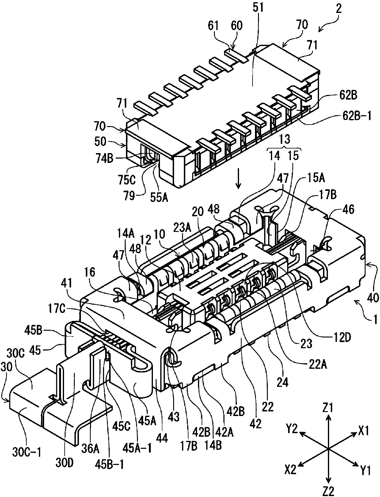
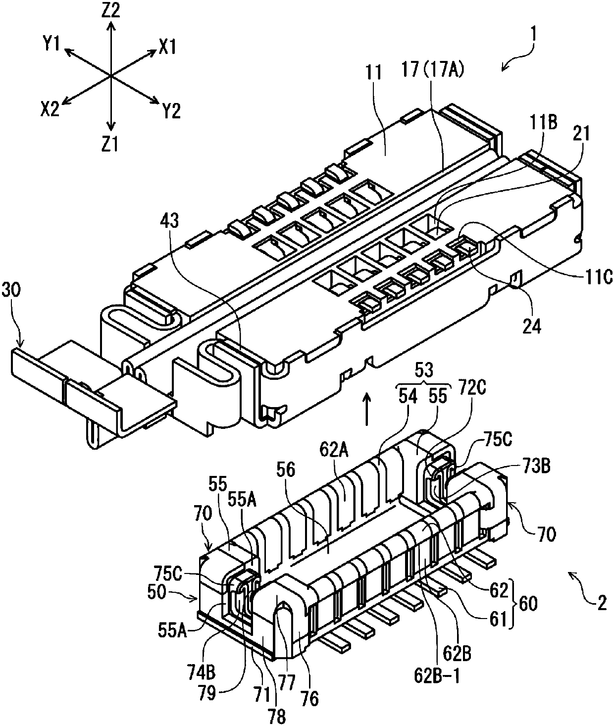
[0038] figure 1 It is a perspective view of the receptacle connector 1 of this embodiment and the plug connector 2 fitted to this receptacle connector 1 from above, and shows the state before connector fitting. figure 2 is to make figure 1 The perspective view showing the receptacle connector 1 and the plug connector 2 upside down is a perspective view showing a posture in which the plug connector 2 is fitted from below.
[0039] The receptacle connector 1 of the present embodiment and the plug connector 2 which is the target connector of the receptacle connector 1 are electrical connectors for circuit boards respectively disposed on the mounting surfaces of different circuit boards (not shown), and constitute The direction at right angles to the surface of each circuit board ( figure 1 The up and down direction (Z-axis direction)) is used as the connector assembly in the plugging and unplugging direction. For receptacle connector 1, the connector mating direction relative...
no. 2 approach >
[0123] In the first embodiment, the locked metal fitting 30 of the plug connector 2 is manufactured by bending a metal plate member, but instead, the plate portion of the locking metal fitting may be formed by, for example, bending a metal member as follows. Made by machining.
[0124] Figure 8A is a perspective view of the plug connector 102 of the second embodiment, Figure 8B is maintained at Figure 8A A perspective view of the locked metal member 170 of the plug connector 102 of FIG. The plug connector 102 of the second embodiment differs from the plug connector 2 of the first embodiment only in the shape of the metal piece to be locked. The plug-side housing and terminals of the plug connector 102 have the same configuration as the plug-side housing and terminals of the above-mentioned plug connector 2, so the same reference numerals as those in the first embodiment are assigned and descriptions are omitted (see Figure 7A ).
[0125] Figure 8A The illustrated pl...
no. 3 approach >
[0129] Figure 9A is a perspective view of the plug connector 202 of the third embodiment, Figure 9B is maintained at Figure 9A A perspective view of the locked metal member 270 of the plug connector 202 of FIG. The plug connector 202 of the third embodiment differs from the plug connector 102 of the second embodiment only in the shape of the metal piece to be locked. The plug-side housing and terminals of the plug connector 202 have the same configuration as the plug-side housing and terminals of the above-mentioned plug connector 102, so the same reference numerals as those in the second embodiment are assigned and descriptions thereof are omitted (see Figure 9A ).
[0130] Figure 9A The illustrated plug connector 202 is fitted and connected to the receptacle connector 1 of the first embodiment. Such as Figure 9B As shown, the locked metal piece 270 of the plug connector 202 is a material in any direction of the connector fitting direction (Z-axis direction), the ...
PUM
 Abstract
Description
Claims
Application Information
 - R&D Engineer
- R&D Manager
- IP Professional
- Industry Leading Data Capabilities
- Powerful AI technology
- Patent DNA Extraction
Browse by: Latest US Patents, China's latest patents, Technical Efficacy Thesaurus, Application Domain, Technology Topic, Popular Technical Reports.
© 2024 PatSnap. All rights reserved.Legal|Privacy policy|Modern Slavery Act Transparency Statement|Sitemap|About US| Contact US: help@patsnap.com