
Patsnap Eureka
For R&D, Patsnap Eureka makes reading and utilizing patents & technical documents easy.
Patsnap Eureka AIR
Designed for self-driven R&D workflows. Generate viable solutions, solve complex R&D challenges, empower your innovation with AI.

Patsnap Eureka Materials
Designed for material experts only. Revolutionize your material R&D, from search, analyze, to developing new materials.

TechResearch
Generate reliable direction feasibility study reports for your R&D in just a few steps.

TechSeek
Discover and master advanced knowledge NOW. Basics, ideas, possibilities, all at once.

TechMind
As an expert in R&D Theories, TechMind can generates customized viable solutions instantly.

TechRisk
Analyze your overall solution with one click, know your potential R&D risks in advance.

TechMonitor
Get weekly tech updates, stay abreast of the latest tech innovations and key insights.
Transmission shaft head unit
A head unit and drive shaft technology, applied in the field of machinery, can solve the problems of unstable connection relationship, increased labor costs, structural deformation, etc., and achieve the effects of instant cooling of the connection relationship, reasonable overall design, and extended service life.
- Summary
- Abstract
- Description
- Claims
- Application Information
AI Technical Summary
Problems solved by technology
Method used
Image

Examples
Embodiment Construction
[0012] The present invention will be further explained below in conjunction with the accompanying drawings and embodiments.
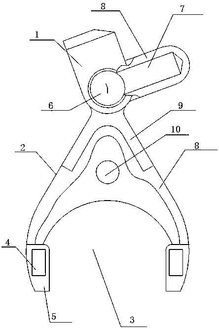
[0013] Such as figure 1 As shown, a transmission shaft head unit includes a limit rotation unit 1 and a clamp unit 2 movably connected with the limit rotation unit 1, the clamp unit 2 is a clamp unit with an arc-shaped opening 3, and the arc-shaped The opening 3 is symmetrically provided with a magnetic clamping block 4, and the magnetic clamping block 4 is wrapped with an elastic wear-resistant layer 5. The position-limiting rotation unit 1 includes a rotating shaft 6 and a rotating block 7 adapted to the rotating shaft 6. The limit rotation unit 1 and the clamp unit 2 are provided with a cooling cavity 8, and the cooling cavity 8 is provided with cooling liquid. A reinforcement piece 9 is provided at the joint between the limit rotation unit 1 and the clamp unit 2 . The rotating block 7 is a rotating block made of magnetic material. The clamp unit ...
PUM
 Abstract
Description
Claims
Application Information
 - R&D Engineer
- R&D Manager
- IP Professional
- Industry Leading Data Capabilities
- Powerful AI technology
- Patent DNA Extraction
Browse by: Latest US Patents, China's latest patents, Technical Efficacy Thesaurus, Application Domain, Technology Topic, Popular Technical Reports.
© 2024 PatSnap. All rights reserved.Legal|Privacy policy|Modern Slavery Act Transparency Statement|Sitemap|About US| Contact US: help@patsnap.com