
Automatic scanning device of insect images

A technology of automatic scanning and scanning device, applied in image communication, TV, color TV components and other directions, can solve the problem of not too small viewing range, low image definition, deformation of surrounding insect images, etc., to improve the monitoring effect , a large amount of data, the effect of automation

Pending Publication Date: 2018-03-09
宁波鹏博云控科技有限公司
View PDF12 Cites 3 Cited by
  • Summary
  • Abstract
  • Description
  • Claims
  • Application Information

AI Technical Summary

Problems solved by technology

[0003] 1. In the application environment, due to the interference of other equipment placement, the fill light often brings partial shadows to the insect image;
[0004] 2. In the application environment, the fill light will also produce different degrees of reflection on the bottom plate;
[0005] 3. In the application environment, due to the different distances of the light entering the camera from the center of the base plate and the surrounding areas, the light in the center and surrounding areas of the same picture will be uneven;
[0006] 4. In the application environment, due to the different angles between the center of the shooting base plate and the surrounding area, the surrounding insect images will be deformed;
[0007] 5. In the application environment, since the viewfinder range cannot be too small, the camera must be kept at a certain height from the bottom plate. When identifying small insects, the image clarity is obviously low;
[0008] 6. In the application environment, due to the exposure of the camera, insects and a large amount of fine dust, the lens is easy to get dirty. If it is used for a long time without cleaning, the shooting effect will gradually decline

Method used


Image

  • Automatic scanning device of insect images

Examples


Embodiment Construction

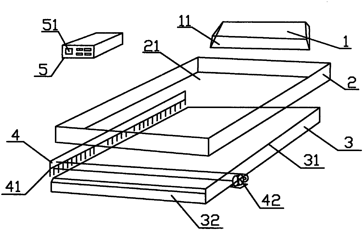
[0020] An automatic insect image scanning device, comprising an insect spraying tube 1, an insect leveling device 2, a scanning device 3, an insect cleaning device 4, and a controller 5, the controller 5 being respectively connected to the insect spraying tube 1, the insect leveling device 2, The scanning device 3 and the insect cleaning device 4, the insect spraying pipe 1 is set above the insect uniforming device 2, a number of sieve holes 21 are opened at the bottom of the insect uniforming device 2, the scanning device 3 is installed under the insect uniforming device 2, and the insect cleaning device 4 is installed at The upper surface of the scanning device 3.

[0021] An opening and closing device 11 controlled by the controller 5 is installed on the insect sprinkling port at the bottom of the insect sprinkling tube 1 to ensure that it opens and closes in time intervals according to the scanning progress, avoids overlapping insect coverage, improves scanning quality and imp...


PUM


Abstract

The invention provides an automatic scanning device of insect images. The automatic scanning device comprises an insect spraying tube, an insect homogenizing device, a scanning device, an insect clearing device and a controller, wherein the controller is separately connected with the insect spraying tube, the insect homogenizing device, the scanning device and the insect clearing device, the insect spraying tube is arranged above the insect homogenizing device, a plurality of sieve holes are formed in the bottom of the insect homogenizing device, the scanning device is installed below the insect homogenizing device, and the insect clearing device is installed on the upper surface of the scanning device. An opening and closing device controlled by the controller is installed on an insect spraying opening at the bottom of the insect spraying tube, the sieve holes have uniformly distributed equal apertures or different apertures, and the scanning device is composed of a scanning panel anda scanner. The automatic scanning device has the beneficial effects of being real-time to avoid the information loss caused by insect mildew, too late insect extraction and other reasons; being fast:the data transmission system can efficiently provide data for the system terminal; being efficient: the fully automatic mode can provide more accurate data; and being standard: the fully automatic mode ensures more standard sampling and highly unified recognition statistical effect.

Description

Technical field [0001] The invention relates to a scanning device, in particular to a plane image acquisition device mainly used for crop insect automatic identification technology, which adopts a stepwise scanning method from bottom to top to obtain brand-new insect images. Background technique [0002] With the continuous improvement of agricultural technology, crop insect monitoring will inevitably shift from manual identification to automatic identification by electronic equipment. The prerequisite for this recognition technology is to obtain high-quality live insect images. In practical applications, if you take photos of insects by adding fill light from top to bottom, like laboratory insect camera, there will be a series of practical problems. [0003] 1. In the application environment, due to the interference of other equipment placement, the fill light will often bring partial shadows to the insect image; [0004] 2. In the application environment, the fill light will also...

Claims


Application Information

Patent Timeline
Patent Type & Authority Applications(China)
IPC IPC(8): H04N5/225B08B1/00
CPCH04N23/50B08B1/12
Inventor 于博
Owner 宁波鹏博云控科技有限公司
Learn More