
Convenient power line network laying device

A laying device and electric power technology, applied in the field of electric power, can solve the problems of inability to realize oblique soil slope compaction, inconsistent soil layer density, and uneven settlement of the soil foundation, so as to improve the work efficiency of knocking, convenient operation, The effect of reducing the labor load of workers

Inactive Publication Date: 2018-03-09
吴波挺
View PDF4 Cites 0 Cited by
  • Summary
  • Abstract
  • Description
  • Claims
  • Application Information

AI Technical Summary

Problems solved by technology

The traditional way is to use a shovel to tap the ground after backfilling the soil layer. This method is time-consuming and laborious, and the density of the soil layer is inconsistent. In case of heavy rain, the soil foundation is easy to settle unevenly, and it is easy to cause the pole to fall. At present, some automatic operating machines cannot achieve tilting. The compaction of the slope of the corner is very restrictive

Method used


Image

  • Convenient power line network laying device
  • Convenient power line network laying device
  • Convenient power line network laying device

Examples


Embodiment Construction

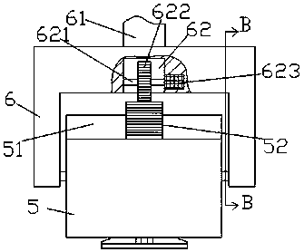
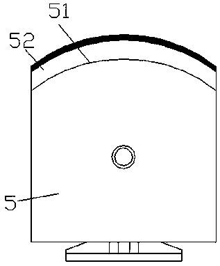
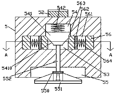
[0020] like Figure 1-Figure 5 As shown, a convenient power line network laying device of the present invention includes a fixed frame 6 and a main body 5 mounted in the fixed frame 6 in a swivel fit. The top of the main body 5 is provided with a curved surface 51, and the curved surface 51 is fixed A tooth curved surface 52 is provided, and an inclination adjustment device connected with the tooth curved surface 52 is provided in the fixed frame 6 on the upper side of the tooth curved surface 52. The bottom surface of the main body 5 is provided with a first concave A groove 55 is provided, and the inside of the main body 5 on the upper side of the first concave groove 55 is provided with a left and right elongated first slide cavity 53, and the middle end of the inner top wall of the first slide cavity 53 communicates with a second slide cavity. Sliding cavity 54, the second sliding cavity 54 is smoothly connected with a cone block 541, the second sliding cavity 54 on the to...


PUM


Abstract

The invention discloses a convenient electric power line network laying device, which comprises a fixed frame and a main body which is mounted in the fixed frame by turning and fitting. There is an inclination adjustment device that is dynamically connected with the curved surface of the teeth. The bottom surface of the main body is provided with a first concave groove. The main body on the upper side of the first concave groove is provided with a left and right elongated first sliding cavity. The first sliding cavity The middle end of the top wall in the cavity communicates with a second sliding cavity, and the second sliding cavity is smoothly fitted with a cone block. The second sliding cavity on the top of the cone block is provided with a first elastic member, and a probe Into the convex part of the first sliding cavity, the push shaft that is elongated up and down is connected smoothly in the main body between the bottom of the first sliding cavity and the top of the first concave groove; the present invention has simple structure, convenient operation, and improves work efficiency and quality.

Description

technical field [0001] The invention relates to the field of electric power technology, in particular to a convenient power line network laying device. Background technique [0002] In order to improve the urban and rural power distribution, it is necessary to increase the laying of the power line network in a reasonable and orderly manner. Before erecting the cables, it is necessary to dig a hole in the bottom surface to fix the cable rack. The stability of the cable rack is directly related to the safety and quality of the line erection. . The traditional way is to use a shovel to tap the ground after backfilling the soil layer. This method is time-consuming and laborious, and the density of the soil layer is inconsistent. In case of heavy rain, the soil foundation is easy to settle unevenly, and it is easy to cause the pole to fall. At present, some automatic operating machines cannot achieve tilting. The compaction of the slope of the corner is highly restrictive. Con...

Claims


Application Information

Patent Timeline
Patent Type & Authority Applications(China)
IPC IPC(8): E04H12/34E02D3/046
CPCE04H12/347E02D3/046
Inventor 吴波挺
Owner 吴波挺
Learn More