
A movable sludge dehydration device and method

A sludge dewatering and mobile technology, applied in water/sewage treatment equipment, water/sludge/sewage treatment, sludge treatment, etc., can solve the problems of high moisture content, small scale, low relative benefits, etc. Low, easy-to-focus effect

Pending Publication Date: 2018-03-09
JINAN BOAN AUTOMATIC CONTROL TECH +1
View PDF4 Cites 5 Cited by
  • Summary
  • Abstract
  • Description
  • Claims
  • Application Information

AI Technical Summary

Problems solved by technology

[0003] Due to the scattered and small-scale rural water treatment facilities in my country, sewage treatment plants cannot build sludge treatment facilities for this situation. Therefore, the current sludge treatment methods are crude and simple, which greatly affects the rural ecological environment.
[0004] The existing sludge dehydration treatment is mainly based on the large-scale dehydration production line of the sewage treatment plant. The dehydrators are in the form of a centrifugal type and a plate-and-frame type. These two types of dehydration machines are large in size and power consumption, and need to be equipped with a pump room , medicine supply tanks, etc.
For distributed and small-scale sewage treatment facilities, the amount of sludge produced is small, the cost of building a sludge dehydration workshop is high, and the relative benefit is low. The volume of sludge removal and transportation is large and the moisture content is high.

Method used


Image

  • A movable sludge dehydration device and method
  • A movable sludge dehydration device and method

Examples


Embodiment Construction

[0025] The present invention will be further described below in conjunction with the accompanying drawings and embodiments.

[0026] It should be pointed out that the following detailed description is exemplary and is intended to provide further explanation to the present application. Unless defined otherwise, all technical and scientific terms used herein have the same meaning as commonly understood by one of ordinary skill in the art to which this application belongs.

[0027] It should be noted that the terminology used here is only for describing specific implementations, and is not intended to limit the exemplary implementations according to the present application. As used herein, unless the context clearly dictates otherwise, the singular is intended to include the plural, and it should also be understood that when the terms "comprising" and / or "comprising" are used in this specification, they mean There are features, steps, operations, means, components and / or combina...


PUM


Abstract

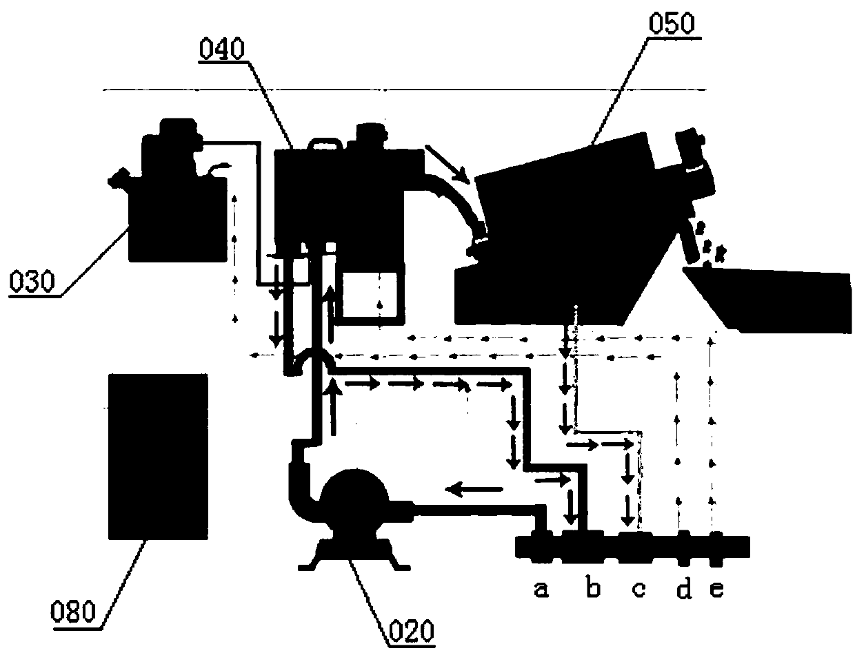
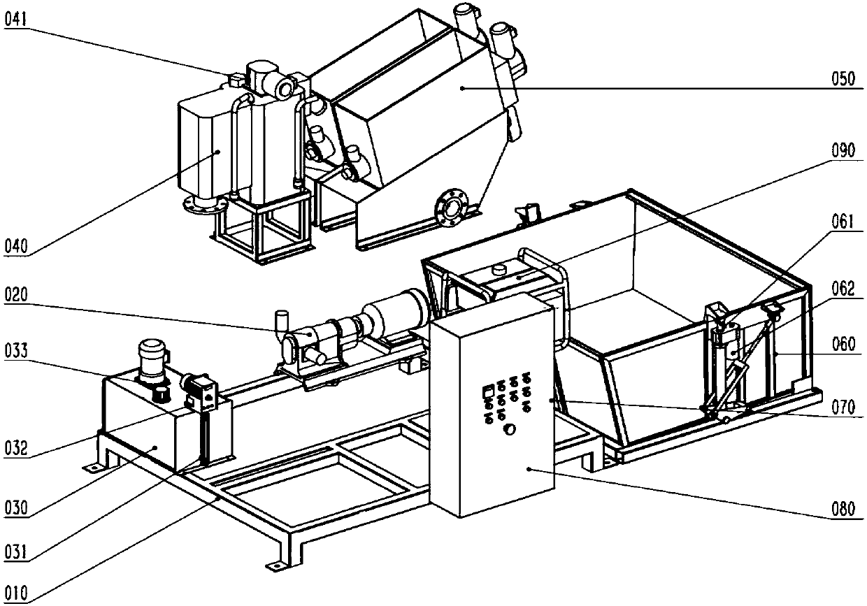
A movable sludge dehydration device and method are disclosed. The device includes a sludge sucking unit, a chemical soaking unit, a flocculation unit, a dehydration unit, a self-discharging sludge storage unit and an electric control unit which can be mounted to a vehicle as a whole. The sludge sucking unit is connected to the chemical soaking unit, the flocculation unit, the dehydration unit andthe self-discharging sludge storage unit in order through a pipeline. Sludge is fed into the dehydration device through the sludge sucking unit. The sludge subjected to flocculation by the flocculation unit is dehydrated by the dehydration unit. The electric control unit is separately connected to the sludge sucking unit, the chemical soaking unit, the flocculation unit, the dehydration unit and the self-discharging sludge storage unit to provide electrical drive for normal operation of the whole dehydration device. The device integrates sludge sucking, chemical supplying, flocculation, dehydration, storage, transportation and power supply, overcomes a sludge removing and transportation difficult problem for distributed and small-size wastewater treatment facilities, particularly rural wastewater treatment facilities, and allows the amount of sludge removing and transportation to be reduced, thus facilitating further centralized and resource-recovering treatment of the sludge.

Description

technical field [0001] The invention relates to the technical field of sludge dewatering, in particular to a mobile sludge dewatering device and method. Background technique [0002] When the sewage plant treats sewage, a large amount of sludge is produced every day. The sludge contains a large amount of easily decomposed organic matter, which has the potential to pollute the environment, and has a certain impact on the water treatment equipment, and even causes the equipment to fail to operate normally. However, the traditional sludge treatment method has a high moisture content, a large volume, difficult transportation, and stacking damages the environment. Therefore, before the sludge is transported, dehydrating the sludge to reduce the moisture content, reduce the organic matter content and reduce the volume weight has become an effective method for sludge treatment. [0003] Due to the scattered and small-scale rural water treatment facilities in my country, sewage tre...

Claims


Application Information

Patent Timeline
Patent Type & Authority Applications(China)
IPC IPC(8): C02F11/12C02F11/14
CPCC02F11/121C02F11/14C02F2303/06C02F2201/008
Inventor 李显杰郭雪松周忠涛高远柴超吕广鹏
Owner JINAN BOAN AUTOMATIC CONTROL TECH
Learn More