
A Centrally Controlled Aircraft Ground Measurement and Control System Network

A measurement and control system and aircraft technology, applied in the field of aircraft measurement and control, can solve the problems of large and complex software structure, increased failure rate of parts and components, classification management, etc., and achieve the effect of avoiding long preparation time, reducing labor cost, and avoiding failure rate.

Active Publication Date: 2021-03-23
JIANGXI HONGDU AVIATION IND GRP
View PDF15 Cites 0 Cited by
  • Summary
  • Abstract
  • Description
  • Claims
  • Application Information

AI Technical Summary

Problems solved by technology

Due to the complex functions of the ground measurement and control system, the configuration of the traditional ground measurement and control equipment test preparation stage is cumbersome and the operation is complicated. When the application scene changes, the system needs to be re-deployed, and the process is complicated
The software structure is huge and complex, and the interface integration is not high. Users often need to switch between multiple interfaces to complete the corresponding business.
Various communication network parameters need to be completed and injected manually, and the network planning and establishment takes a long time, which cannot meet the needs of flexible organization and temporary allocation
[0003] In addition, the traditional ground measurement and control equipment is relatively independent, and is generally realized by the structure of the industrial computer. When used, it is generally moved with the model task. The frequent transportation and movement of the equipment will cause the problem of unstable operation of the equipment and an increase in the failure rate of parts and components year by year. Due to the independence of the ground telemetry station, it is difficult to effectively classify and manage the telemetry data of the entire life cycle of the aircraft through information technology

Method used


Image

  • A Centrally Controlled Aircraft Ground Measurement and Control System Network
  • A Centrally Controlled Aircraft Ground Measurement and Control System Network

Examples


Embodiment Construction

[0015] Below in conjunction with accompanying drawing and embodiment the present invention will be further described:

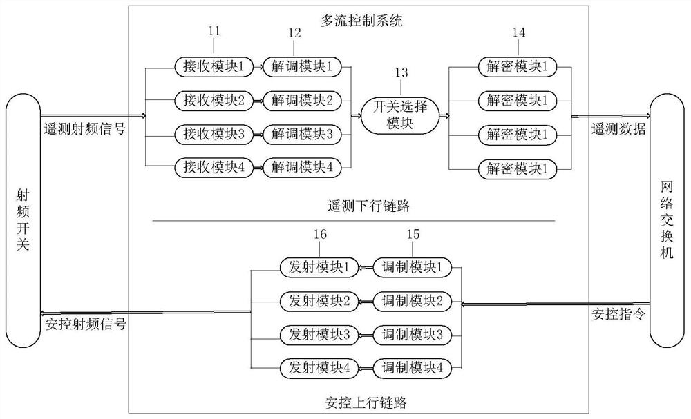
[0016] see figure 1 The aircraft ground measurement and control system network controlled by the center of the present invention includes a measurement and control antenna 1, an antenna end radio frequency optical transceiver 2, a radio frequency optical fiber cable 3, a radio frequency switch 4, a multi-stream measurement and control system 5, a display and control terminal 6, a network switch 7 and a computer 8, and the center End radio frequency optical transceiver 10. Among them, the radio frequency optical transceiver 10 at the center end, the radio frequency switch 4, the multi-stream measurement and control system 5, the display and control terminal 6, the network switch 7 and the computer 8 are centrally placed and connected to form a measurement and control center 9, which is used to complete the unified planning and overall layout of test tasks. Un...


PUM


Abstract

The invention belongs to the technical field of aircraft measurement and control, and relates to a center-controlled aircraft ground measurement and control system network. The system network comprises a measurement and control antenna (1), an antenna end radio frequency optical transmitter and receiver (2), a radio frequency optical cable (3), a radio frequency switch (4), a multi-stream measurement and control system (5), a display control terminal (6), a network interchanger (7), a computer (8) and a center end radio frequency optical transmitter and receiver (10). The center end radio frequency optical transmitter and receiver (10), the radio frequency switch (4), the multi-stream measurement and control system (5), the network interchanger (7), the display control terminal (6) and thecomputer (8) are concentrated to form a measurement and control center (9) which is used for completing the coordinative operation of the unified scheduling, overall layout, unified command and dispatch and multi-type aircraft test of a test task. By means of the network, a center control function is realized, operation is convenient, parameter configuration is convenient, whole-period data management is easy to realize, and large practical application value is achieved.

Description

technical field [0001] The invention belongs to the technical field of aircraft measurement and control, and relates to a center-controlled aircraft ground measurement and control system network. Background technique [0002] As an important part of the aircraft scientific research test, the ground measurement and control system is the only platform for obtaining data during the entire test process, and plays an indispensable role. Due to the complex functions of the ground measurement and control system, the configuration of the traditional ground measurement and control equipment test preparation stage is cumbersome and the operation is complicated. When the application scene changes, the system needs to be re-deployed, and the process is complicated. The software structure is huge and complex, and the interface integration is not high. Users often need to switch between multiple interfaces to complete the corresponding business. Various communication network parameters n...

Claims


Application Information

Patent Timeline
Patent Type & Authority Patents(China)
IPC IPC(8): B64F5/60B64G3/00
CPCB64G3/00B64F5/60
Inventor 马文超姚先秀赵广超高茜聂荣唐旭周曦周之丽李科连张玉新张玮熊琼王先发
Owner JIANGXI HONGDU AVIATION IND GRP
Learn More