
Control method applied to full-automatic cleaning device for welding gun of industrial arc welding robot

A technology of cleaning device and control method, applied in the direction of cleaning welding torches and welding accessories, etc., can solve the problems of poor flow of shielding gas, damage to the gun head, hidden dangers, etc., so as to reduce labor intensity, improve product quality, and eliminate the need for manual labor. effect of intervention

Active Publication Date: 2018-03-09
南通市慧冠智能科技有限公司
View PDF9 Cites 1 Cited by
  • Summary
  • Abstract
  • Description
  • Claims
  • Application Information

AI Technical Summary

Problems solved by technology

When the robot is finished welding, a large amount of residue will be generated on the inner wall of the welding torch head, which will affect the appearance and quality of the welding process, and cause certain damage to the torch head, which needs to be disassembled and cleaned at regular intervals
[0003] Industrial arc welding industrial robots replace manual work and work continuously in an environment with a relatively high duty cycle. Due to the working conditions of gas shielded welding, it is impossible to completely avoid spatter during the short-circuit transition welding process, and the particles formed by spatter If the welding time is too long, the spatter will accumulate too much, and it is easy to form a clogged cavity, resulting in poor flow of protective gas, which cannot protect the weld seam, thus forming welding defects , if the robot stops at this time, there will be safety hazards if the welding spatter in the sleeve is manually cleaned, and it is easy to lose the efficient welding effect of robot automation

Method used


Image

  • Control method applied to full-automatic cleaning device for welding gun of industrial arc welding robot
  • Control method applied to full-automatic cleaning device for welding gun of industrial arc welding robot
  • Control method applied to full-automatic cleaning device for welding gun of industrial arc welding robot

Examples


Embodiment Construction

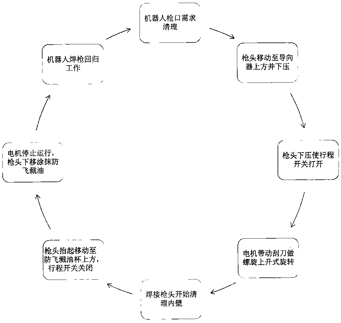
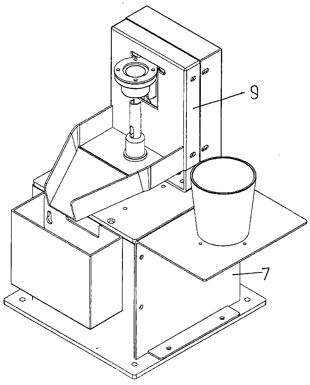
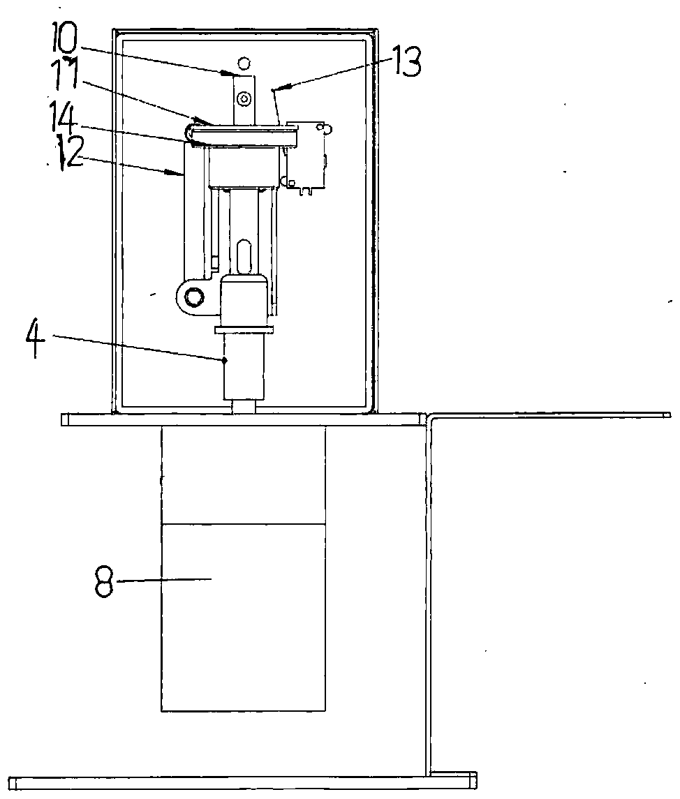
[0020] A control method applied to a fully automatic cleaning device for welding torches of industrial arc welding robots, comprising a base frame 7, a motor 8 is mounted on the base frame, a slide rail box 9 is arranged above the base frame, a slide rail 10 is mounted on the slide rail box, and a slide rail is mounted on the slide rail The slider 19 fixedly connected by the rail connector 11; the upper part of the rail connector is arranged on the upper end of the guide, and is fixedly connected with the upper end of the guide, and the central center hole of the rail connector and the central center hole of the guide are on the same axis , the bottom of the slide rail connector extends below the guide, the lower end of the spring 12 is fixedly connected with the bottom of the slide rail connector, and the upper end of the spring is fixedly connected with the slide rail box; The stroke switch 13 of motor work. The scraper includes a cutter head 1, the cutter head is in the for...


PUM


Abstract

The invention discloses a control method applied to a full-automatic cleaning device for a welding gun of an industrial arc welding robot. When cleaning is needed, a control system instructs a gun head of the welding robot to move to the position above a guider, the guider is pressed downwards and moves down, a travel switch contact leaves a slider, a travel switch is switched on, a motor drives ascraper to clean residues on the inner wall of the welding gun head, the residues are discharged automatically into a waste box through the scraper, the welding gun returns to work after being cleaned, the guider returns to the initial position under the stress action of a spring, the travel switch contact is propped against the slider again, the travel switch is switched off, the motor stops running, and the cleaning process is finished; the robot returns to a welding working position, the control system stops and resets automatically and waits for next cleaning action instruction of the robot, and cleaning is performed regularly. Manual cleaning of splashing welding residues on the inner wall of the welding gun can be replaced, efficiency is increased, and manual labor intensity is reduced.

Description

technical field [0001] The invention relates to a control method applied to a fully automatic cleaning device for an industrial arc welding robot welding torch. Background technique [0002] With the mass production of modern industrial robots, a large number of problems have also been found. When the robot is finished welding, a large amount of residue will be generated on the inner wall of the welding torch head, which will affect the appearance and quality of the welding process, and cause certain damage to the torch head, which needs to be disassembled and cleaned at regular intervals. [0003] Industrial arc welding industrial robots replace manual work and work continuously in an environment with a relatively high duty cycle. Due to the working conditions of gas shielded welding, it is impossible to completely avoid spatter and particles formed by spatter during short-circuit transition welding. If the welding time is too long, the spatter will accumulate too much, wh...

Claims


Application Information

Patent Timeline
Patent Type & Authority Applications(China)
IPC IPC(8): B23K9/32
CPCB23K9/32B23K9/328
Inventor 朱芳顾菁辛毅宋昶霖周建美
Owner 南通市慧冠智能科技有限公司
Learn More